Clamping device

A technology of clamping device and fixing device, which is applied in the direction of positioning device, tool changing device, clamping, etc., and can solve the problem of high cost

Active Publication Date: 2014-06-04
AMANN GIRRBACH
View PDF4 Cites 5 Cited by
  • Summary
  • Abstract
  • Description
  • Claims
  • Application Information

AI Technical Summary

Problems solved by technology

Of course, this costs a lot

Method used


Image

  • Clamping device
  • Clamping device
  • Clamping device

Examples


Embodiment Construction

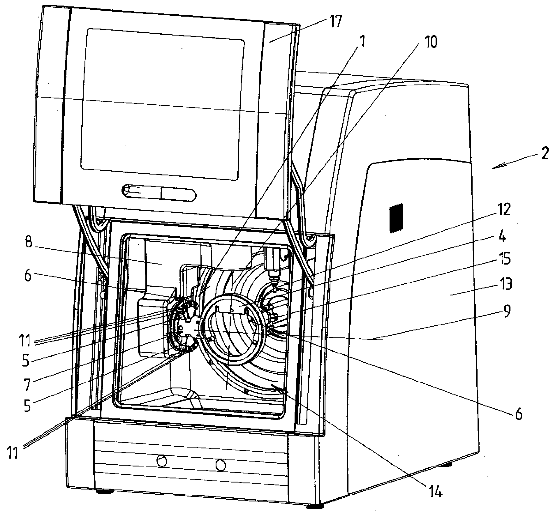
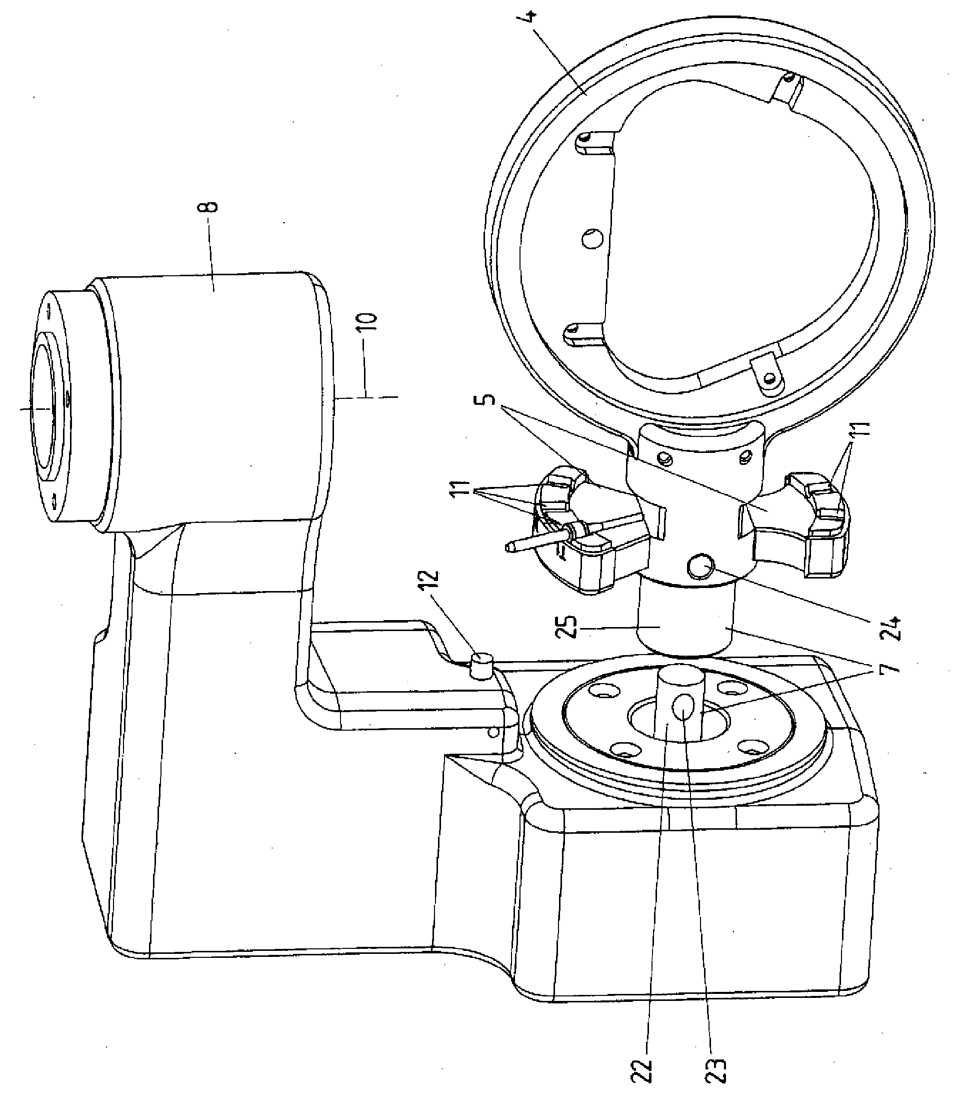
[0027] The processing machine tool 2 shown in the drawing has a housing 13 with a processing cavity 14 arranged therein. The dental workpiece 3 to be machined during the machining process is arranged in the machining cavity 14 . The workpiece is held in the machining cavity 14 by means of the clamping device 1 during the machining process and can also be positioned by means of the clamping device 1 in relation to the tool carrier head 15 or in a position arranged at the tool carrier head 15 precisely for the respective machining step. tool 6 in a defined position for machining. exist figure 1The dental workpiece 3 to be machined, not shown, is arranged on the workpiece holder 4 either directly or indirectly, for example via an intervening frame surrounding the dental workpiece. According to the invention, the workpiece holder 4 and the tool holder 5 form a common component, which can be fastened or fastened alternatively to the carrier of the clamping device 1 by means of a...


PUM


Abstract

The invention relates to a clamping device (1) for a machine tool (2) for machining at least one dental workpiece (3), wherein the clamping device (1) has at least one workpiece carrier (4) for accommodating the dental workpiece (3) during machining, wherein at least one tool holder (5) for holding at least one, preferably a plurality of cutting tools (6) for machining the dental workpiece (3) is arranged, preferably fixedly, on the workpiece carrier (4) and the workpiece carrier (4) and the tool holder (5) are fastened or fastenable together as one component on a carrier of the clamping device (1) in an exchangeable manner by means of a fastening device (7) that is non-destructively releasable, preferably without a tool.

Description

technical field [0001] The invention relates to a clamping device for a processing machine tool for machining at least one dental workpiece, wherein the clamping device has at least one workpiece holder for receiving the dental workpiece during processing. Background technique [0002] Clamping devices of this type are known in various embodiments from the prior art. For example, document WO 2009 / 100863 A2 shows a clamping device in which two rings are arranged in a pivotable manner relative to each other, wherein a plate-shaped workpiece holder can be fixed in the inner ring, while the The processed dental workpiece is held in the through-hole of the workpiece holder in a closed peripheral manner. [0003] The various dental workpieces to be machined in the prior art consist of different materials. This is the main reason why machining machines for machining such dental workpieces require not only one tool but often several tools. A second reason for the need to use diff...

Claims


Application Information

Patent Timeline
IPC IPC(8): A61C13/00B23Q1/25
CPCB23Q1/5443A61C13/0022B23Q3/06A61C13/00B23Q1/25B23Q3/15706A61C13/0003F04C2270/0421Y10T483/17Y10T483/1795Y10T483/132Y10T409/305824Y10T483/1873Y10T483/1743Y10T409/30392A61C13/1016E21B17/00B23Q3/15526B23Q3/15546B23Q3/15506B23C1/02B23Q11/0891B23Q1/5406B23Q1/5412
Inventor T.科奇
Owner AMANN GIRRBACH
Why Eureka
Try Eureka