
Combined heat pump and hot water heating system

A combined system and hot water technology, which is applied in the direction of heating and cooling combination, residential hot water supply system, heating system, etc., can solve the problem of increasing the overall building equipment cost, operating cost and occupied space, environmental thermal pollution, and energy loss and other issues, to achieve the effect of improving the adaptability of the working environment, good actual use requirements, and high energy utilization

Active Publication Date: 2016-03-02
DALIAN POLYTECHNIC UNIVERSITY
View PDF11 Cites 0 Cited by
  • Summary
  • Abstract
  • Description
  • Claims
  • Application Information

AI Technical Summary

Problems solved by technology

During the cooling operation in summer, the air source heat pump air conditioner needs to discharge a large amount of condensation heat to the outdoor atmosphere when it is operating to cool the room, which will cause energy loss and environmental thermal pollution.
When heating in winter, the working efficiency of the air source heat pump air conditioner decreases sharply. When the temperature drops to a certain level, the air source heat pump air conditioner can hardly work normally. Therefore, the use of air source heat pump air conditioners in low temperature areas in winter has poor economic benefits and Difficulty running etc.
[0003] If air source heat pump air conditioners and heat pump water heaters are installed at the same time in commercial buildings or residential buildings, it will increase the overall equipment cost, operating cost and occupied space of the building.

Method used


Image

  • Combined heat pump and hot water heating system
  • Combined heat pump and hot water heating system
  • Combined heat pump and hot water heating system

Examples


Embodiment Construction

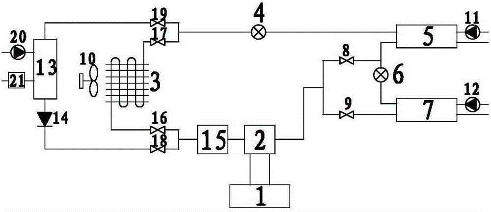
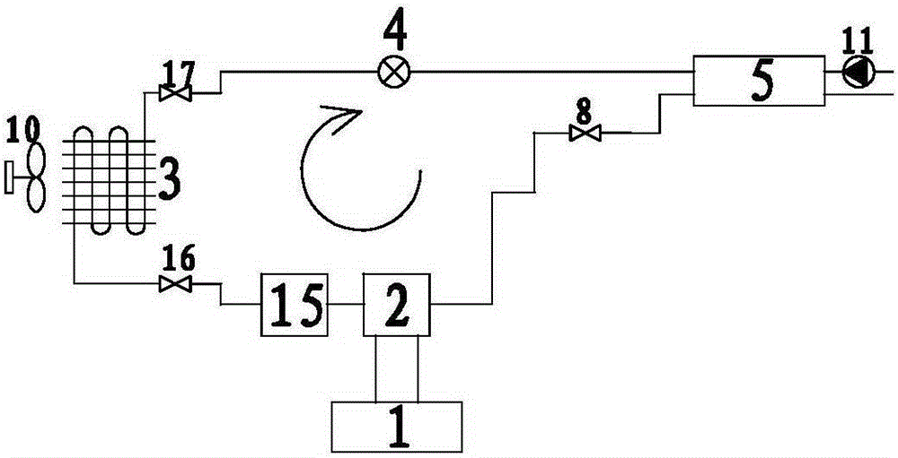
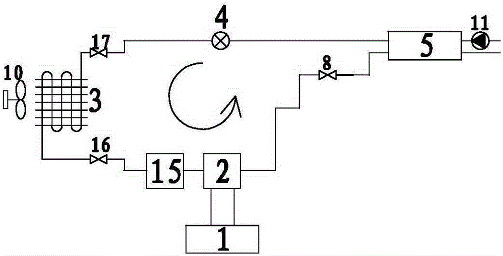
[0028] figure 1 It is a schematic structural diagram of the heat pump and hot water heating combined system of the present invention. The combined heat pump and hot water heating system of the present invention includes a compressor 1, a four-way valve 2, a gas-liquid separator 15, and an air The first switching valve 16 of the source branch, the air source heat exchanger 3, the second switching valve 17 of the air source branch, the first switching valve 18 of the freezing branch, the check valve 14, the freezing evaporator 13, the freezing branch The second switch valve 19, the first expansion valve 4, the air conditioner heat exchanger 5, the second expansion valve 6, the hot water heat exchanger 7, the air conditioner heat exchanger switch valve 8, and the hot water heat exchanger switch valve 9; : Compressor 1, four-way valve 2, first switching valve 16 of air source branch, second switching valve 17 of air source branch, first switching valve 18 of freezing branch, secon...


PUM


Abstract

The invention discloses a combined heat pump and hot water heating system, which belongs to the technical field of air compression refrigeration and air conditioning. A combined heat pump and hot water heating system of the present invention includes a compressor (1), a four-way valve (2), a gas-liquid separator (15), and a first switch of an air source branch connected in sequence through a refrigerant pipeline. Valve (16), air source heat exchanger (3), air source branch second switching valve (17), freezing branch first switching valve (18), check valve (14), freezing evaporator ( 13), the second switch valve (19) of the freezing branch, the first expansion valve (4), the air conditioner heat exchanger (5), the second expansion valve (6), the hot water heat exchanger (7), the air conditioner Heater switch valve (8), hot water heat exchanger switch valve (9). Compared with the prior art, the present invention has reliable performance, high operation efficiency, high energy utilization rate and less thermal pollution to the environment.

Description

technical field [0001] The invention belongs to the technical field of air compression refrigeration and air conditioning, and more specifically, belongs to a vapor compression and low-temperature heat source hybrid heat pump device system that utilizes energy in the air for refrigeration, heating and domestic hot water supply. Background technique [0002] The air-source heat pump air-conditioning device adopts a vapor compression refrigeration cycle system. The vapor compression refrigeration cycle system usually uses the low-grade energy in the outdoor atmosphere to provide thermal equipment for the air-conditioning system as a cold and heat source. At present, air-source heat pumps have been used in residential and commercial buildings. Has been widely used. The air source heat pump air conditioner can produce cold water and hot water, and use cold water or hot water as the medium to directly deliver cold or hot air to the room through the air conditioner terminal, and p...

Claims


Application Information

Patent Timeline
Patent Type & Authority Patents(China)
IPC IPC(8): F24H4/02F25B41/20
CPCF24D17/02F24D19/1006F24H4/02F25B13/00F25B29/003F25B41/00F25B49/02F25B2313/02741F25B2600/25F25B41/26F25B41/20F25B41/31
Inventor 王海文张俊杰梁亮张明张俊清
Owner DALIAN POLYTECHNIC UNIVERSITY
Learn More