Industrial airtight container and connection method thereof

A technology of sealed containers and connection methods, which is applied in the field of industrial sealed containers and their connections, and can solve the problems of high processing environment requirements, long construction period, and welding quality depending on workers' operation level and proficiency

Active Publication Date: 2014-06-04
SUS LAB FOR IND SCI & TECH
View PDF5 Cites 2 Cited by
  • Summary
  • Abstract
  • Description
  • Claims
  • Application Information

AI Technical Summary

Problems solved by technology

[0004] 1. Because there are oil pipelines and other devices in the fuel tank section, once the fuel tank section is welded, it is equivalent to the process passage of the fuel tank section being sealed off, and the inspection and maintenance of the fuel tank becomes extremely difficult or even impossible.
[0005] 2. The welding quality depends on the worker's operation level and proficiency, and the quality of the fuel tank compartment is difficult to guarantee
Moreover, electron beam welding is used, which has potential safety hazards and has high requirements for the processing environment.
[0006] 3. Subsequent finishing and grinding of the weld seam is required after welding, which is time-consuming and laborious
[0007] 4. Welding requires a long construction period and low production efficiency, making it difficult to meet industrial needs
[0008] 5. Since the containers are connected together by welding, once a part is deformed or destroyed, the entire container needs to be replaced as a whole, and its use cost is high

Method used


Image

  • Industrial airtight container and connection method thereof
  • Industrial airtight container and connection method thereof
  • Industrial airtight container and connection method thereof

Examples


Embodiment Construction

[0039] In order to make the technical solution of the present invention clearer, the present invention will be further described in detail below in conjunction with the accompanying drawings and specific embodiments.

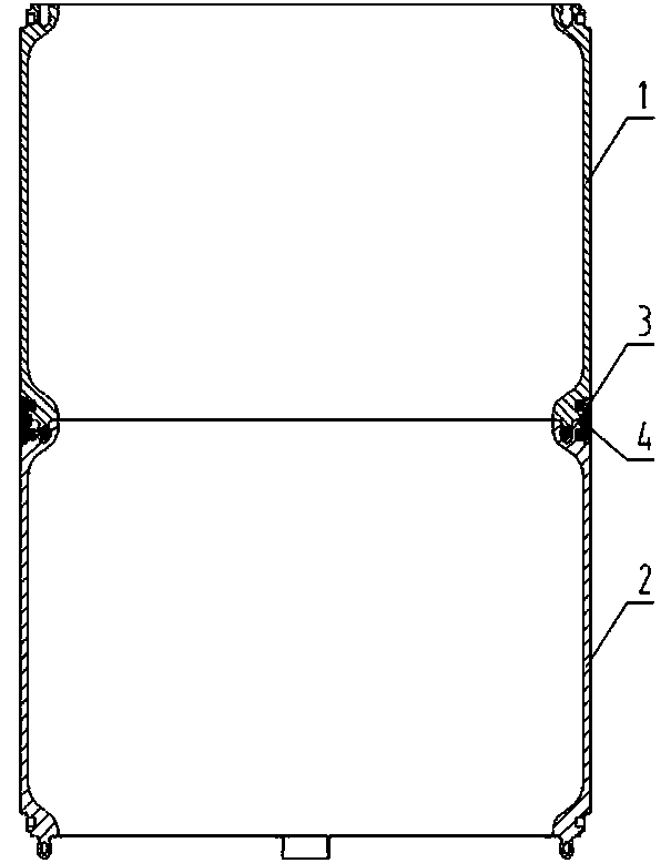
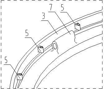
[0040] Please refer to Fig. 1 and Fig. 2, Fig. 1 is a schematic diagram of partial connection of a specific embodiment of the industrial sealed container provided by the present invention; Fig. 2 is a partial cross-sectional view of the industrial sealed container shown in Fig. 1 .

[0041]It should be noted that the industrial airtight container mentioned in this article refers to a metal or non-metal container with relatively high hardness and a large extension size. It is necessary to ensure both the connection strength and the tightness at the same time to meet the needs of industrial use. Obviously, this method can also be used for daily necessities. At the same time, the first sealed chamber 1 and the second sealed chamber 2 are only the definitions of th...


PUM


Abstract

The invention discloses an industrial airtight container. The industrial airtight container comprises a first air-tight bin and a second air-tight bin, wherein the first air-tight bin and the second air-tight bin are arranged in sequence in the extension direction of the industrial airtight container. The industrial airtight container further comprises a connecting device which is connected with the first air-tight bin and the second air-tight bin. The connecting device comprises a fastening and connecting snap fastener plate, seal rings, male snap fasteners, and female snap fasteners matched with the male snap fasteners, wherein the fastening and connecting snap fastener plate surrounds the periphery of the first air-tight bin and the periphery of the second air-tight bin in the circumferential direction; the seal rings are arranged between the fastening and connecting snap fastener plate and the first air-tight bin and between the fastening and connecting snap fastener plate and the second air-tight bin. The industrial airtight container is simple in connection structure, high in connection efficiency, low in cost, detachable, and convenient to maintain and examine. Meanwhile, the invention further provides a connection method of the industrial airtight container. The connection method realizes connection of the industrial airtight container and lowers the usage cost of the industrial airtight container.

Description

technical field [0001] The invention relates to the field of industrial airtight container manufacturing, in particular to an industrial airtight container and a connection method thereof. Background technique [0002] There are many kinds of industrial containers. Due to their large volume, many containers need to be formed in two or more stages to form a whole, and require certain strength requirements such as compressive and tensile strength, especially for some working conditions where the external environment is relatively harsh. Next, the requirements for the container are even higher. For example, the fuel tank compartment of a missile aircraft is required to have a long service life, good corrosion resistance, sealing performance, fatigue resistance, and less strain on temperature changes. Therefore, the processing of this type of industrial container is difficult, and has always been one of the bottlenecks in my country's industrial development. [0003] Taking th...

Claims


Application Information

Patent Timeline
IPC IPC(8): B65D90/08
Inventor 苏章仁
Owner SUS LAB FOR IND SCI & TECH
Why Eureka
Try Eureka