
Ticket production device and ticket production method

A single-ticket, cut-off unit technology, applied to printing devices, temperature recording methods, printing, etc., can solve problems such as defective, lost, and interference cutting

Active Publication Date: 2014-06-04
SEIKO EPSON CORP
View PDF6 Cites 8 Cited by
  • Summary
  • Abstract
  • Description
  • Claims
  • Application Information

AI Technical Summary

Problems solved by technology

[0004] However, in the above-mentioned printers, if the time for the operator to take out the slips is delayed, the issued slips may accumulate at the paper outlet of the printer or drop from the paper outlet.
If the bills are piled up, there may be a problem that the accumulated bills interfere with the tip of the automatic cutter to cause cutting failure, or cut the stacked bills again to produce small cut pieces, which will adversely affect the operation of the printer.
In addition, if a single ticket falls, problems such as loss and misallocation may occur

Method used


Image

  • Ticket production device and ticket production method
  • Ticket production device and ticket production method
  • Ticket production device and ticket production method

Examples


no. 1 approach

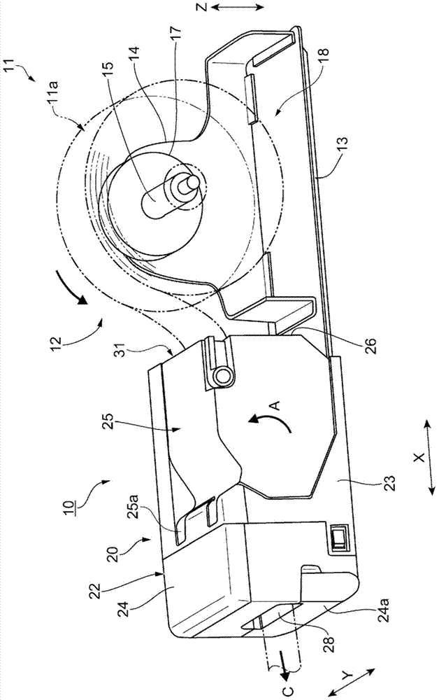
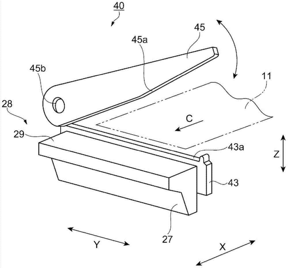
[0066] Here, refer to figure 2 as well as Figure 4 The recording paper posture detection unit according to the first embodiment will be described. Figure 4 It is a figure explaining the recording paper posture detection unit which concerns on 1st Embodiment, (a) is a perspective view seen from the recording paper discharge direction, (b) is a schematic view seen from S direction in figure (a) , (c) is a schematic view observed from the T direction in Figure (a). Figure 4 The shown X direction, Y direction and Z direction represent the same figure 1 The indicated X direction, Y direction, and Z direction are the same directions.

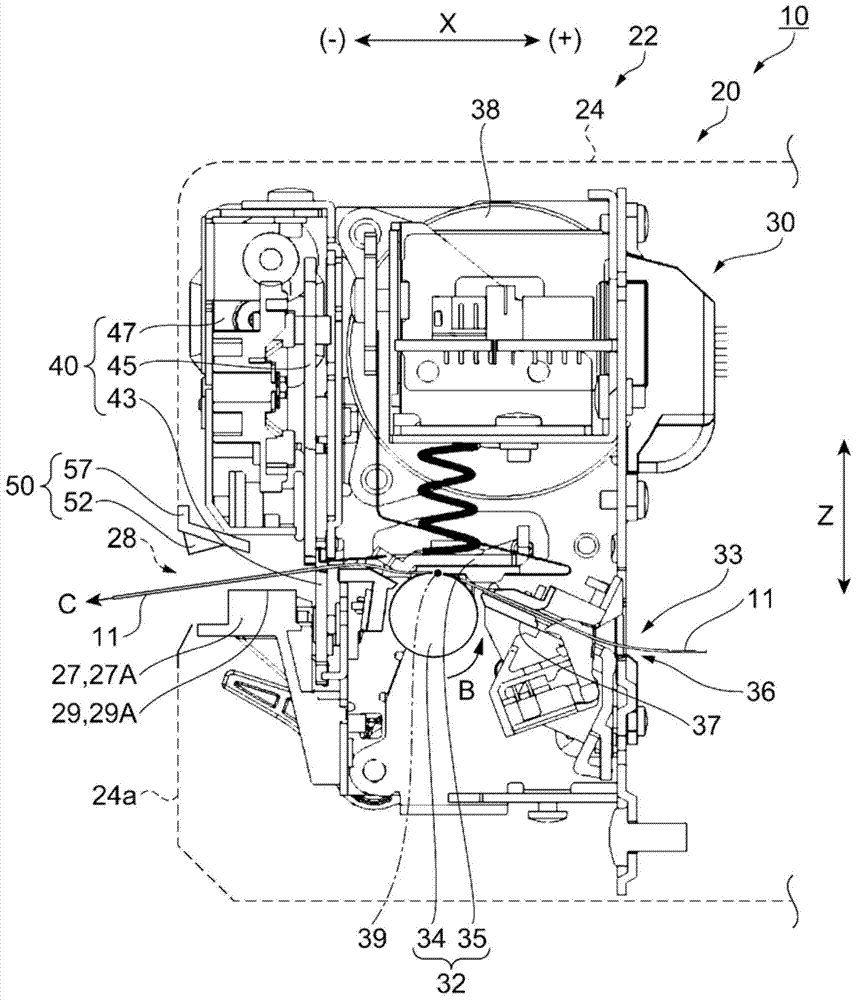
[0067] Such as figure 2 As shown, the recording paper posture detection unit 50 is disposed at a position facing the paper guide surface 29 of the above-mentioned paper table 27 at the paper outlet 28 portion of the exterior case 22, that is, at a position opposite to the completed printing remaining on the paper guide surface 29. The positi...

no. 2 approach

[0093] Here, refer to Figure 6 A recording paper posture detection unit according to a second embodiment will be described. Figure 6 It is a figure explaining the recording paper attitude|position detection means in 2nd Embodiment. Figure 6 The shown X direction, Y direction and Z direction represent the same figure 1 The indicated X direction, Y direction, and Z direction are the same directions. In addition, the same code|symbol is attached|subjected to the same structure and content as 1st Embodiment, and description is abbreviate|omitted.

[0094] Such as Figure 6 As shown, the recording paper posture detection unit 50A of the second embodiment includes a plurality of detectors 60A arranged in a row over the entire paper width along the paper width direction of the recording paper 11 on the paper guide surface 29A of the paper table 27A. Therefore, the plurality of detectors 60A face the back surface of the printed recording paper 11 remaining on the paper table 27...


PUM


Abstract

A ticket production device 20 that cuts continuous recording paper 11 printed with information and produces a ticket includes a paper conveyance means 32 that conveys the recording paper 11 through a paper conveyance path 33; a printing means 35 that prints information on the recording paper 11 conveyed by the paper conveyance means 32; a paper cutting means 34 that cuts the recording paper 11 on which information was printed into a ticket of a specific length; a paper position detection means 50 that detects the position of the recording paper 11 waiting at a paper exit 28; and a control means that integrally controls these other means. When the paper position detection means 50 detects the position of the recording paper 11 changed, the control means operates the paper cutting means 40 and produces a ticket based on the detection result from the paper position detection means 50.

Description

technical field [0001] The present invention relates to a ticket issuing device and a ticket issuing method for printing a ticket with information. Background technique [0002] Conventionally, individual tickets such as receipts, coupons, and labels have been used in various fields such as logistics and business flow. A printer with an automatic cutter is used as the ticket issuing device for issuing these tickets. This type of printer prints information on long strips of recording paper, and uses an automatic cutter to sequentially cut the recording paper into predetermined lengths and issue them as tickets. The automatic cutter is arranged in the downstream part of the paper conveying path that reaches the paper outlet via the printing position. The cut slip is manually taken out by the operator and handed over to the customer (for example, refer to Patent Document 1). [0003] Patent Document 1: Japanese Patent Laid-Open No. 2004-268207 [0004] However, in the above...

Claims


Application Information

Patent Timeline
Patent Type & Authority Applications(China)
IPC IPC(8): B41J11/42B41J11/66
CPCB41J3/4075B41J11/663B41M5/30B41J11/703G06C29/00
Inventor 行徳保广远藤克幸
Owner SEIKO EPSON CORP
Learn More