
Device for manufacturing portable rope head

A technology outside the rope head and device, which is applied in the field of making portable rope head devices. It can solve the problems that the 1 end of the lifting rope deviates from the plastic-coated center, the rope head is loose, and the plastic-coated plastic is not formed, so as to improve work efficiency and pull-off force. Improve, improve the effect of stability

Inactive Publication Date: 2014-06-04
十堰奕郎工贸有限公司
View PDF5 Cites 4 Cited by
  • Summary
  • Abstract
  • Description
  • Claims
  • Application Information

AI Technical Summary

Problems solved by technology

There are also handbags for handbags, the structure of which can only be used for lighter objects
[0003] The current overmolding of the handle rope head 2 is to first cut the rope 1 according to the length of the product, and then place the two ends in the cavity for pre-embedded injection molding; because the end of the rope 1 in the cavity is pressed by the sealing surface , the other end is in a free state. Due to the flow of plastic and the imbalance of internal pressure during injection molding, the end of the lifting rope 1 will deviate from the center of the plastic coating, or even float on the surface; the deviation of the plastic coating 2 of the lifting rope 1 will cause Insufficient tightening force will affect the use function of the lifting rope. In severe cases, safety accidents will occur. The processed products such as figure 2 shown
[0004] Furthermore, the ends of the cut rope will be loose due to the self-elasticity of the rope, which will cause the plastic wrap to be out of shape, wasting time and raw materials

Method used


Image

  • Device for manufacturing portable rope head
  • Device for manufacturing portable rope head
  • Device for manufacturing portable rope head

Examples


Embodiment Construction

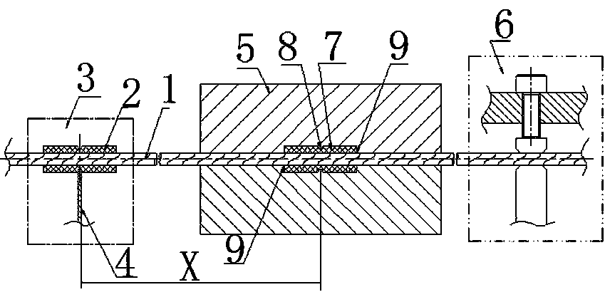
[0019] The present invention as image 3 shown.

[0020] A device for making a portable rope head, comprising a cutting device 1, a plastic wrapping device 5 is provided on one side of the cutting device 3 at a fixed length X, and a tensioning device 6 is arranged outside the plastic wrapping device 5, wherein the cutting device 3 is based on its The center of the cutting knife 4 and the overmolding device 5 has a fixed length X, and the mold cavity of the overmolding device 5 is provided with a double overmolding head cavity 7, and is provided with a guide rope groove 9 from both sides, and the tensioning device 6 is provided with a lift Rope 1.

[0021] The cavity 7 of the double-packed plastic head is provided with an even boundary knife flute 8 .

[0022] The cutting device 3, the double overmolding head cavity 7 of the overmolding device 5, and the tensioning device 6 are arranged in parallel.

[0023] During production, the lifting rope 1 is an overall length, and one...


PUM


Abstract

The invention provides a device for manufacturing a portable rope head. A plastic coating device is arranged at one side of a cut-off device in a fixed length manner; a tensioning device is arranged outside the plastic coating device, wherein the length of the cut-off device is fixed by the centers of a cutter and the plastic coating device; a dual-plastic-coating-head die cavity with dividing cutter edges is arranged in the die cavity of the plastic coating device, rope guiding slots are formed in two sides of the dual-plastic-coating-head die cavity, and a portable rope is arranged on the tensioning device; a plurality of cut-off devices, dual-plastic-coating-head die cavities of the plastic coating devices and tensioning devices are arranged in parallel. The portable rope has an integrated length in production, one end of the portable rope is straightened at the cut-off device, so that the portable rope and the tension device form a straight line; plastic injection is performed in the rope guiding slots of the dual-plastic-coating-head die cavity, so that two plastic coating heads are formed on the portable rope once; fixed-length circulating plastic coating is performed from the middle parts of the two plastic coating heads to the cut-off device, and the plastic coated portable rope which is drawn out of the cut-off device is cut at the cut position to form a portable rope finished product; portable ropes can be constantly and continuously produced in a reciprocating circulation manner.

Description

technical field [0001] The invention relates to a device and a method for making a rope head of a propane or plastic rope, in particular to a device for making a hand-held rope head. Background technique [0002] The plastic wrapping standard of the portable rope head is as follows: figure 1 , is to wrap plastic 2 at both ends of a lifting rope 1, which can bear a weight of more than 50kg, especially for the lifting rope of heavy objects, such as the lifting rope of the battery, the requirement is that the two ends of the lifting rope 1 are wrapped in the bag. Plastic 2 is in the middle so that it can withstand the force of heavier objects. There is also the hand rope of the handbag, and its structure can only be applicable to lighter objects. [0003] The current overmolding of the handle rope head 2 is to first cut the rope 1 according to the length of the product, and then place the two ends in the mold cavity for pre-embedded injection molding; because the end of the r...

Claims


Application Information

Patent Timeline
Patent Type & Authority Applications(China)
IPC IPC(8): B29C45/14B29C45/17
CPCB29C45/14336B29C45/17
Inventor 杨记生
Owner 十堰奕郎工贸有限公司
Learn More