
Cam plotting instrument

A plotter and cam technology, applied in the field of plotters, can solve the problems of large volume and limited functions, and achieve the effect of compact structure, easy operation and simple use

Inactive Publication Date: 2014-05-28
XIAN TECHNOLOGICAL UNIV
View PDF6 Cites 9 Cited by
  • Summary
  • Abstract
  • Description
  • Claims
  • Application Information

AI Technical Summary

Problems solved by technology

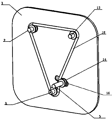
[0003] The purpose of this invention is to provide a cam plotter to overcome the problems of large volume and limited functions in existing plotters

Method used


Image

  • Cam plotting instrument
  • Cam plotting instrument
  • Cam plotting instrument

Examples


Embodiment 1

[0026] Embodiment 1: Draw the cam law curve by the profile of eccentric cam, promptly use eccentric cam:

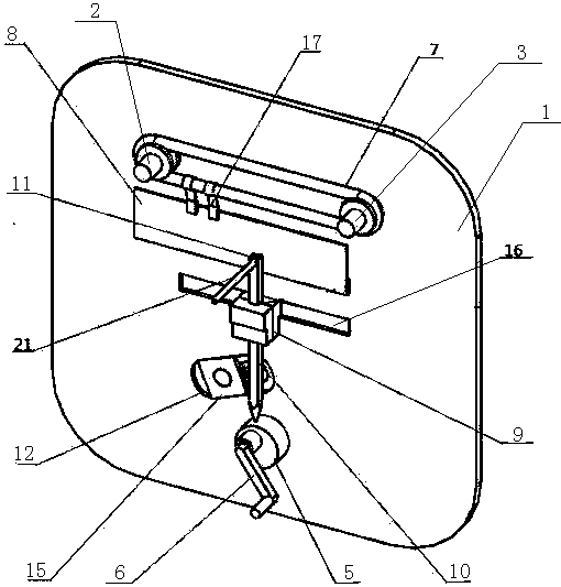
[0027] see figure 2 , turn the handle 6, so that the first rotating shaft 2 connected with the handle 6 also rotates accordingly, and the first rotating shaft 2 drives the pulleys on the second rotating shaft 3 and the third rotating shaft 4 to rotate through the pulley, and then the second rotating shaft 3 and the third rotating shaft 4 also rotate with the same angular velocity thereupon, so that the horizontal transmission belt 7 also rotates, and the horizontal transmission belt 7 is connected with the drawing board 8 by the buckle 17, so that the drawing board 8 moves in the horizontal direction, and at the same time, The rotation of the handle 6 will drive the eccentric cam 5 to rotate, and push the push rod 10 to move up and down, thereby driving the pencil to move up and down. Finally, the movement of the drawing board 8 and the movement of the pencil draw the r...

Embodiment 2

[0029] Embodiment 2: Draw the cam profile by the motion law of the grooved cam, that is, use the grooved cam:

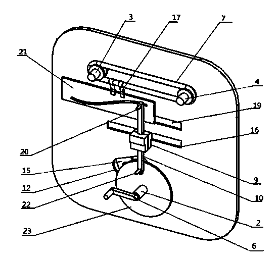
[0030] see image 3 , first, push the grooved cam 21, so that the push rod 10 moves up and down according to the law of motion; at the same time, push the grooved cam 21 to move the buckle 17 to move horizontally, thereby driving the horizontal conveyor belt 7 to rotate, and then driving the second rotating shaft 3 and The third rotating shaft 4 rotates, and then drives the transmission belt to move, so that the first rotating shaft 2 rotates at the same angular velocity, and then drives the circle chart 23 to rotate, and finally makes the regular cam outline drawn on the circle chart 23 by a pencil.

[0031] The present invention is primarily concerned with the relationship between cam motion characteristics and profile. The design weight of this cam motion demonstrator is 2kg. It can adapt to the different teaching requirements of centering cam mechanism and eccen...


PUM


Abstract

The invention relates to a cam plotting instrument. Because of the large size and the arrangement of a laboratory, the conventional cam plotting instrument is not suitable for teachers to carry out demonstration in class, and has few functions, cannot demonstrate outline regulations of multiple cams, and thus has limited teaching effect, only has a function of demonstrating the motion regulation, cannot design the outline of a cam in an inversed direction. The cam plotting instrument comprises a base plate, a first rotating shaft, a second rotating shaft and a third rotating shaft penetrate through the base plate and are distributed in an inverted triangular shape; a transmission device is arranged on one side of the base plate; a plotting device is arranged on the other side of the base plate; the transmission device and the plotting device are connected through the first rotating shaft, the second rotating shaft and the third rotating shaft. The cam plotting instrument is simple and reliable in structure, light in weight, simple and convenient to operate, can help students to master the knowledge easily and can be used for a long time.

Description

technical field [0001] The invention relates to a plotter, especially a cam plotter. Background technique [0002] Existing cam plotters are bulky and are not suitable for teachers to demonstrate in class due to the display in the laboratory. Moreover, they have a single function and cannot perform demonstrations of various cam contour laws, and the teaching effect is limited; only demonstration The function of the law of motion, but the outline of the cam cannot be reversely designed. Contents of the invention [0003] The purpose of the present invention is to provide a cam plotter to overcome the problems of large volume and limited functions in existing plotters. [0004] In order to solve the above technical problems, the technical solution of the present invention is: a cam plotter, including a base plate, on which the first rotating shaft, the second rotating shaft and the third rotating shaft are pierced and arranged in an inverted triangle; The other side of th...

Claims


Application Information

Patent Timeline
IPC IPC(8): G09B25/02
Inventor 千学明段兰李林瀚王帅李伟
Owner XIAN TECHNOLOGICAL UNIV
Learn More