
light guide plate

A technology of light guide plate and light guide structure, applied in the field of light guide plate, can solve the problem of unoptimized light uniformity and light output efficiency, and achieve the effect of avoiding the problem of light spot and reducing the number of use.

Active Publication Date: 2016-08-17
RADIANT GUANGZHOU OPTO ELECTRONICS
View PDF4 Cites 0 Cited by
  • Summary
  • Abstract
  • Description
  • Claims
  • Application Information

AI Technical Summary

Problems solved by technology

[0005] However, the above-mentioned existing design, through microscopic observation, the light uniformity and the light output efficiency of each angle are still not optimized, and there is room for further improvement.

Method used


Image

  • light guide plate
  • light guide plate
  • light guide plate

Examples


Embodiment Construction

[0020] Before the present invention is described in detail, it should be noted that in the following description, similar components are denoted by the same numerals.

[0021] refer to Figure 4 , 5 , is the first preferred embodiment of the light guide plate 3 of the present invention, comprising a light incident surface 31, a light exit surface 32 located adjacent to the light incident surface 31, a first light guide structure 33, and a second light guide structure34. The first light guide structure 33 is disposed on the light incident surface 31 . The first light guide structure 33 has a plurality of first semi-arc bodies 331 that are contiguously juxtaposed, and the central angle of each first semi-arc body 331 is defined as And the processing ratio of the first semicircular arc bodies 331 is R1. The second light-guiding structure 34 is arranged on the light-emitting surface 32, and the second light-guiding structure 34 has a plurality of second semi-circular arcs 341...


PUM


Abstract

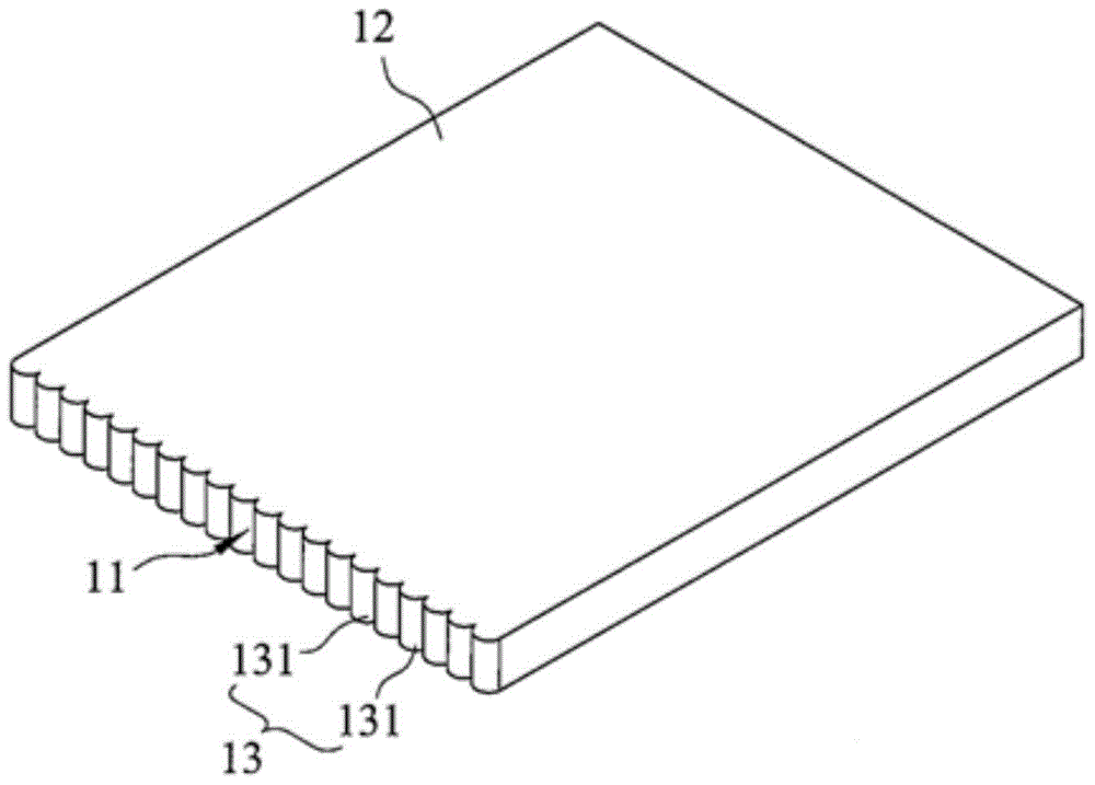
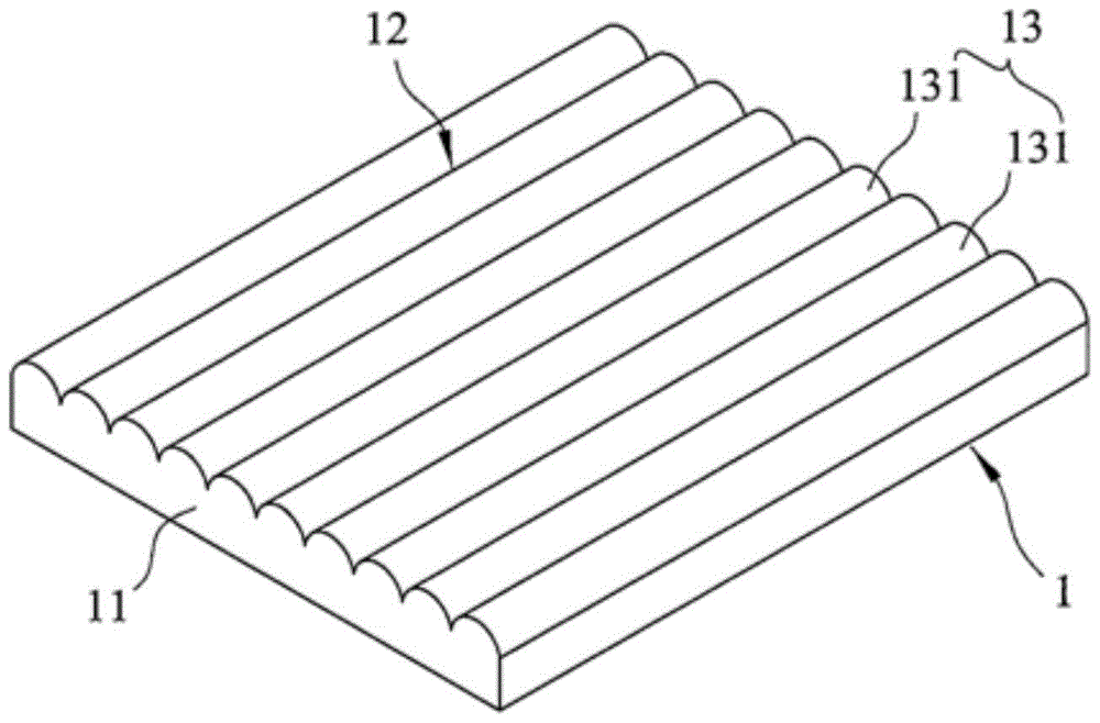
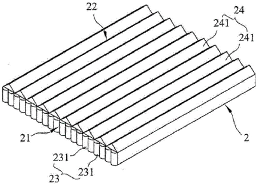
A light guide plate includes a light entry surface with first elongated elements, and a light exit surface with second elongated elements. Each of the first and second elongated elements serves to guide light, and has a cross-section in a shape of a circular segment.

Description

[0001] This application claims the priority of the Taiwan patent application filed on December 26, 2013 with the application number 102148426 and the title of the invention as "light guide plate", the entire contents of which are incorporated in this application by reference. technical field [0002] The present invention relates to the technical field of flat panel display, and more specifically relates to a light guide plate. Background technique [0003] Liquid Crystal Display (LCD) is widely used in Personal Digital Assistant (PDA), mobile phone, camera, etc. Consumer communication or electronic products such as video recorders, notebook computers, desktop monitors, car monitors, and projection TVs. At present, most of the common liquid crystal displays on the market are backlight liquid crystal displays, which are mainly composed of a liquid crystal display panel at the front and a backlight module at the back. (Edge Lighting) module and direct type incident light (Bot...

Claims


Application Information

Patent Timeline
Patent Type & Authority Patents(China)
IPC IPC(8): G02B6/00
CPCG02B6/0038G02B6/0016
Inventor 蔡文豪陈蔚轩
Owner RADIANT GUANGZHOU OPTO ELECTRONICS
Learn More