
a brightening film

A technology of brightness-enhancing film and light-gathering layer, which is applied in the direction of diffusing elements, can solve the problems that the incremental effect needs to be improved, and achieve the effects of reducing the number of sheets used, high luminance gain, and cost reduction

Active Publication Date: 2016-03-09
NINGBO DXC NEW MATERIAL TECH
View PDF5 Cites 0 Cited by
  • Summary
  • Abstract
  • Description
  • Claims
  • Application Information

AI Technical Summary

Problems solved by technology

The microprisms on the surface of existing brightness-enhancing films are generally triangular-prism-shaped, and the incremental effect needs to be improved. Generally, a backlight module needs two mutually perpendicular brightness-enhancing films

Method used


Image

  • a brightening film
  • a brightening film

Examples


Embodiment 1

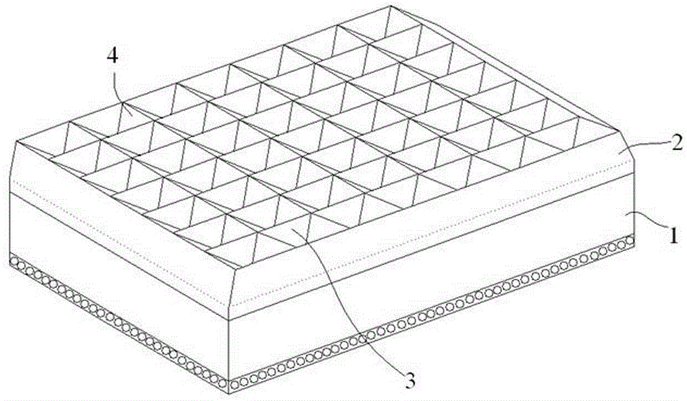
[0018] A brightness enhancement film includes a substrate layer 1 and a light-concentrating layer 2. The surface of the light-concentrating layer 2 has a concave-convex structure in both the length direction and the width direction of the brightness enhancement film. In this embodiment, the concave-convex structure is specifically: on the surface of the light-concentrating layer 2, there are partitions 3 parallel to each other along the length direction of the brightness enhancement film, and an interlayer is formed between adjacent partitions 3, The interlayer has a row of triangular prisms 4 to form a row of triangular prisms, each of the triangular prisms 4 has the same shape, and the two triangular bottom surfaces of the triangular prisms 4 are integrated with the partition 3; the triangular prisms in each interlayer The rows all correspond to each other to form rows of triangular prisms in the width direction of the brightness enhancement film. The upper corners of the tri...

Embodiment 2

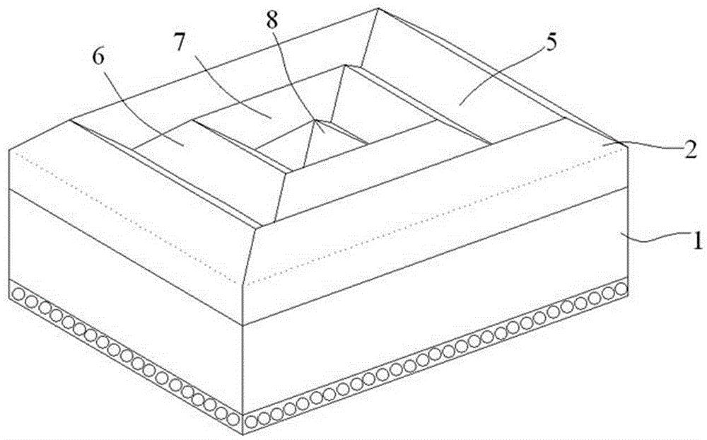
[0023] A brightness enhancement film includes a substrate layer 1 and a light-concentrating layer 2. The surface of the light-concentrating layer 2 has a concave-convex structure in both the length direction and the width direction of the brightness enhancement film. In this embodiment, the concave-convex structure is specifically as follows: the surface of the light-concentrating layer 2 has a regular quadrangular truncated trough-shaped lower groove 5, and the inner side of the lower groove is inclined inward;

[0024] The bottom surface of the lower groove 5 protrudes upwardly with a regular quadrangular pyramid-shaped boss 6, and the four sides of the boss 6 are inclined inward;

[0025] The upper surface of the boss 6 has a downward concave central groove 7 in the shape of a quadrangular pyramid, the inner side of the central groove 7 is inclined inward and the central groove 7 shares a bottom surface with the lower groove 5;

[0026] The bottom surface of the central groove 7 p...


PUM


Abstract

The invention discloses a bright enhancement film which comprises a base material layer and a condensation layer, wherein concave-convex structures are formed in the surface of the condensation layer in the length direction and the width direction of the bright enhancement film. According to the refraction and reflection effects of concave-convex structures in the surface of the condensation layer in the length direction and the width direction on light rays, the convergence angle of the emergent light rays can be adjusted, so that the light rays are converged towards the direction of a user. The bright enhancement film has the light ray converging function in the horizontal and vertical direction, the functions of the conventional two bright enhancement films which are vertically arranged can be realized due to one bright enhancement film in the invention, the number of the used bright enhancement films is reduced, and the cost of a backlight module is further reduced. In addition, according to the backlight module with special requirements on the positive brightness, two bright enhancement films in the invention can be overlapped, and the bright enhancement film in the invention has higher brightness gain compared with the conventional two bright enhancement films which are vertically arranged.

Description

Technical field [0001] The invention relates to a brightness enhancement film. Background technique [0002] Liquid crystal display (LCD, LiquidCrystalDisplay) has become the most common display technology today. Because LCD has the advantages of environmental protection, low energy consumption, low radiation, and soft picture, LCD will be the mainstream display technology in the next few decades. The LCD is a non-luminous display device and requires the use of a backlight module to achieve the display function. Therefore, the performance of the backlight module will directly affect the display quality of the LCD. The main components of the backlight module include: light source, light guide plate, and various optical films. [0003] The optical film of the backlight module mainly includes a reflective film, a brightness enhancement film, and a diffusion film. The function of the brightness enhancement film in the backlight module is to adjust the light outside the viewing angle...

Claims


Application Information

Patent Timeline
Patent Type & Authority Patents(China)
IPC IPC(8): G02B5/02
Inventor 罗培栋江绍钏
Owner NINGBO DXC NEW MATERIAL TECH
Learn More