
Clamp

A clamper and clamping hole technology, which is applied in the direction of drilling equipment, earthwork drilling, drill pipe, etc., can solve the problems of large clamping force, small size, and loss of clamping force, and achieve large clamping force and large size Small, little effect of elasticity

Active Publication Date: 2014-05-28
HUAINAN MINING IND GRP +1
View PDF7 Cites 11 Cited by
  • Summary
  • Abstract
  • Description
  • Claims
  • Application Information

AI Technical Summary

Problems solved by technology

[0005] The invention provides a clamper, which solves the problem that the existing clamper cannot meet the requirements of large opening, large clamping force, and small size at the same time, and the serious loss of clamping force occurs after the slips are worn for a long time. question

Method used


Image

  • Clamp
  • Clamp

Examples


Embodiment Construction

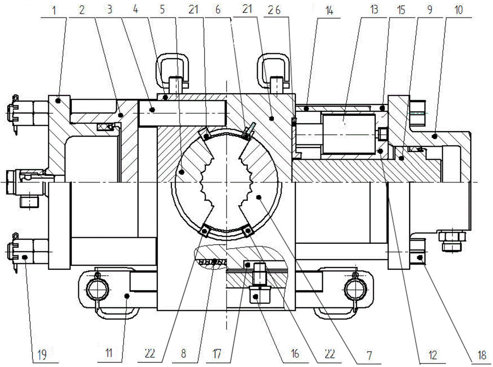
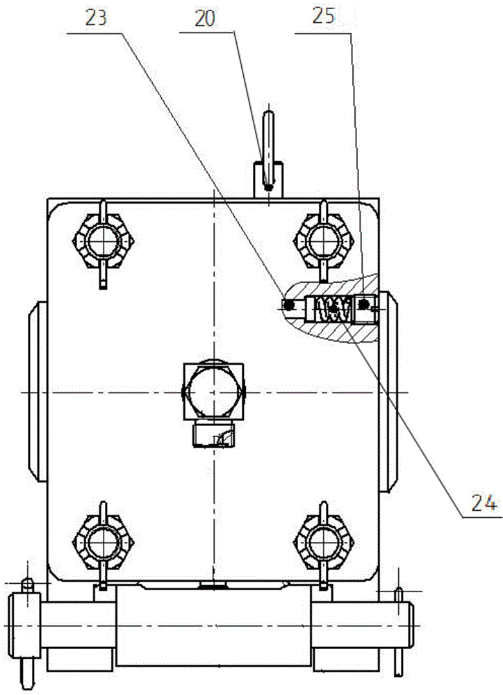
[0038] figure 1 Schematic diagram of the structure of the clamper provided by the embodiment of the present invention, figure 2 for figure 1 left view of . Such as figure 1 and figure 2As shown, the present invention provides a clamper, which includes a left cylinder piston 1, a left cylinder body 2, a top column 3, a left slip seat 4, a left slip seat 5, a right slip seat 6, and a right slip seat 7 , slip seat spring 8, right cylinder piston 9, right cylinder body 10, guide rail 11, nitrogen gas spring seat 12 and nitrogen gas spring 13; left cylinder piston 1 is inserted in left cylinder body 2, and the inner wall of left cylinder piston 1 is connected to the left The inner wall of the oil cylinder body 2 forms a left oil chamber for injecting hydraulic oil, and the ejection end of the left oil cylinder body 2 abuts against one end of the top column 3, and the top column 3 penetrates in the left slip seat 4, and the top column 3 The other end is in contact with the le...


PUM


Abstract

The invention provides a clamp which comprises a left oil cylinder piston, a left oil cylinder body, a jack column, a left slip bowl, a left slip, a right slip bowl, a right slip, a slip bowl spring, a right oil cylinder piston, a right oil cylinder body, a guide rail, a nitrogen spring seat and a nitrogen spring. The left end of the nitrogen spring seat is provided with a nitrogen spring countersink. The right end of the nitrogen spring seat is abutted against the left end of the right oil cylinder body. The ejecting end of the right oil cylinder piston penetrates the central hole of the nitrogen spring seat. The cylinder body of the nitrogen spring is inserted into the nitrogen spring countersink and fixedly connected with nitrogen spring seat. The extending end of the piston of the nitrogen spring is abutted against the right end of the right slip bowl. The clamp is large in opening amount, large in clamping force and small in size, and severe loss of clamping force can be avoided when the slips are abraded after long term use.

Description

technical field [0001] The invention relates to the technology of drilling rig clamping equipment, in particular to a clamper. Background technique [0002] The clamper is an important part of the drilling rig. Its purpose is to clamp the drill pipe in the clamping hole to prevent the drill pipe from slipping in the clamping hole. Unscrew between. [0003] At present, the holder is usually a holder that uses multiple disc springs as elastic elements, and is mainly composed of an oil cylinder, multiple disc springs, slips, slip seats, etc. When the drilling rig stops working or two drills need to be During the unscrewing operation between the rods, the slips should be in a clamped state. When the slips are in a clamped state, multiple butterfly springs are in a pre-compressed state, and the pre-tightening force generated by them acts on the slips through the slip seat. Above, the clamping force for clamping the drill pipe is provided for the slips. The size of the pre-tight...

Claims


Application Information

Patent Timeline
Patent Type & Authority Applications(China)
IPC IPC(8): E21B19/10
Inventor 蒋法文姚亚峰黄晖宋海涛刘文军石璐吴桁刘亦洋
Owner HUAINAN MINING IND GRP
Learn More