
Mask assembly for thin film vapor deposition and manufacturing method thereof

A mask and component technology, applied in the field of mask components and their manufacturing, can solve problems such as poor evaporation and per-mask wrinkles

Active Publication Date: 2014-05-28
SAMSUNG DISPLAY CO LTD
View PDF6 Cites 25 Cited by
  • Summary
  • Abstract
  • Description
  • Claims
  • Application Information

AI Technical Summary

Problems solved by technology

[0005] Furthermore, both ends of the unit mask are stretched while being fixed by the jig. However, the unit mask itself is formed of a thin metal plate, so the unit mask may not be able to withstand the pulling force of the jig and may be pulled. Wrinkles occur at the center of the end fixed to the jig
Wrinkles generated at the end of the unit mask may spread to the center of the unit mask where the opening is formed, causing deposition failure

Method used


Image

  • Mask assembly for thin film vapor deposition and manufacturing method thereof
  • Mask assembly for thin film vapor deposition and manufacturing method thereof
  • Mask assembly for thin film vapor deposition and manufacturing method thereof

Examples


Embodiment Construction

[0033] Hereinafter, embodiments of the present invention will be described in detail with reference to the accompanying drawings so that those skilled in the art to which the present invention pertains can easily implement. The present invention can be realized in various forms, and is not limited to the embodiments described here.

[0034] Throughout the specification, when it is stated that a certain part "includes" a certain constituent element, it means that other constituent elements may also be included unless there is a special statement to the contrary. Also, throughout the specification, when it is described that a layer, film, region, plate, etc. part is located "on" or "over" another part, this includes not only being "immediately above" the other part, but also both. There is another part of the situation in the middle. In addition, the term "on" or "on" means that it is located above or below the object part, and does not mean that it is located on the upper side...


PUM


Abstract

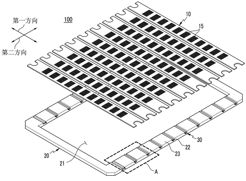
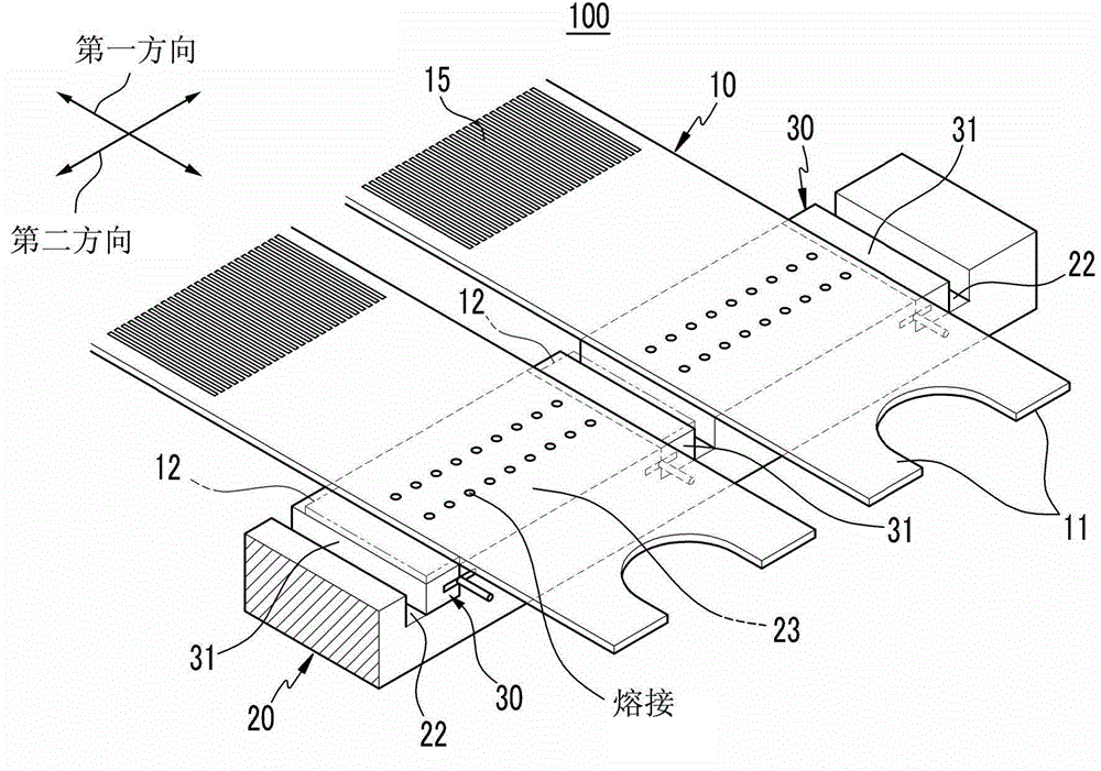
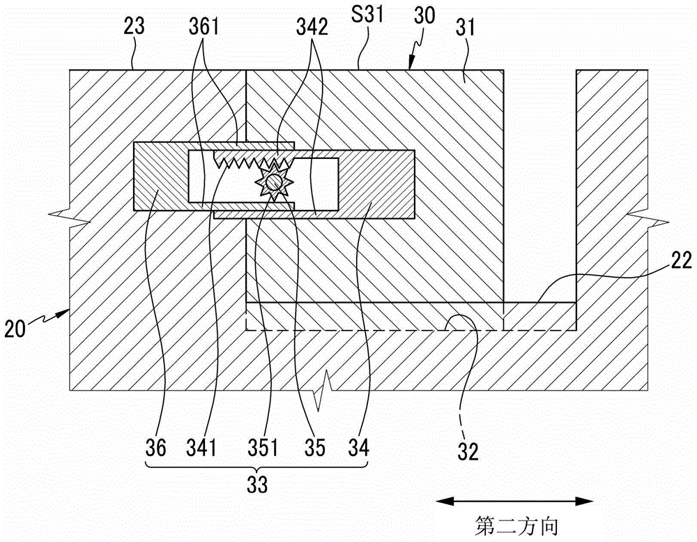
A mask assembly for a thin film deposition includes: a frame main body forming an opening; a plurality of unit masks having both ends fixed to the frame main body in a state that a tension force is applied in a first direction; and an end tension unit installed to the frame main body. The end tension unit moves according to a second direction crossing the first direction between two neighboring unit masks among a plurality of unit masks for tensioning of the unit mask in the second direction.

Description

technical field [0001] The present invention relates to a mask assembly, in particular to a mask assembly used in the thin film evaporation process of an organic light-emitting layer or a metal layer and a manufacturing method thereof. Background technique [0002] Liquid crystal display devices (LCD) and organic light emitting display devices (OLED) are widely used as flat panel display devices. The flat panel display device includes a metal layer with a specific pattern, and for an organic light emitting display device, an organic light emitting layer with a specific pattern is formed for each pixel. As a method of forming the metal layer and the organic light-emitting layer, a vapor deposition method using a mask assembly can be applied. [0003] The mask unit is composed of a mask formed with an opening corresponding to the pattern of the metal layer or the organic light-emitting layer, and a frame supporting the mask. In the divided mask method, a mask is divided into...

Claims


Application Information

Patent Timeline
Patent Type & Authority Applications(China)
IPC IPC(8): C23C14/04C23C14/24
CPCC23C14/042Y10T29/49826H10K71/166H05B33/10H10K71/00
Inventor 金容焕
Owner SAMSUNG DISPLAY CO LTD
Learn More