


Quick Research
Generate reliable direction feasibility study reports for your R&D in just a few steps.

Technical Q&A
Discover and master advanced knowledge NOW. Basics, ideas, possibilities, all at once.

Find Solutions
As an expert in R&D theories, this can generate solutions to your technical problems instantly.

Evaluate Feasibility
Analyze your overall solution with one click, know your potential R&D risks in advance.

Monitor Landscape
Get weekly tech updates, stay abreast of the latest tech innovations and key insights.
Electromagnetic contra-rotating engine
An engine and electromagnetic technology, applied in the direction of electrical components, electromechanical devices, etc., can solve problems such as difficulties, electromotive force phase, frequency difference, high speed of counter-rotating engines, etc., achieve long service life, solve power output problems, and simple structure.
- Summary
- Abstract
- Description
- Claims
- Application Information
AI Technical Summary
Problems solved by technology
Method used
Image


Examples
Embodiment 1
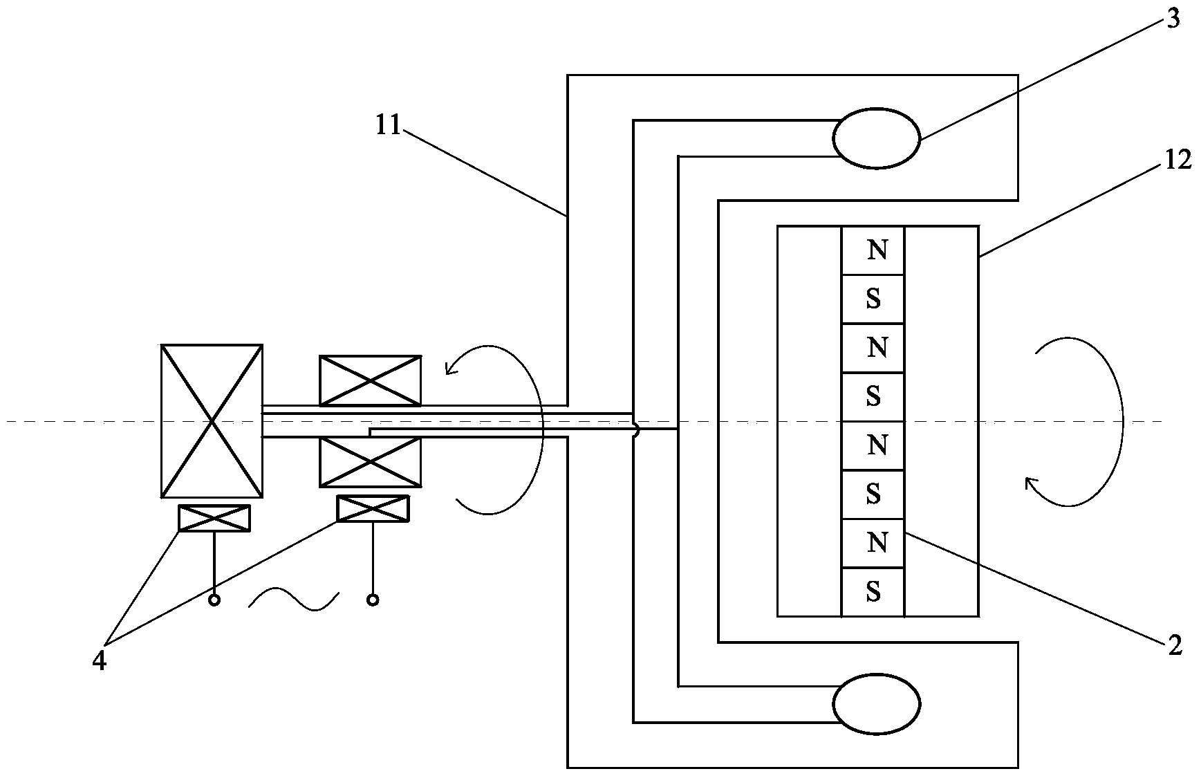
[0027] Such as figure 1 The electromagnetic counter-rotating motor shown includes a counter-rotating motor, a permanent magnet 2 is set on the counter-rotating rotor 12 of the counter-rotating motor, and an inductance coil 3 is set on the forward-rotating rotor 11 of the counter-rotating motor, so The interaction between the permanent magnet 2 and the inductance coil 3 causes an electromotive force to be generated in the inductance coil 3 , and the inductance coil 3 supplies power to the outside through the brush 4 .
Embodiment 2
[0029] Such as figure 2 Shown electromagnetic counter-rotating motor, its difference with embodiment 1 is:
[0030] The permanent magnet 2 is instead arranged on the counter-rotating body 11 , and the induction coil 3 is instead arranged on the counter-rotating body 12 .
Embodiment 3
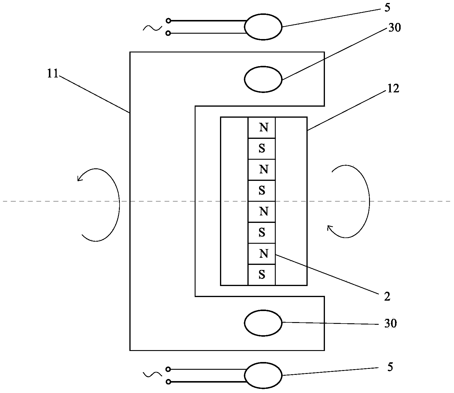
[0032] Such as image 3 Shown electromagnetic counter-rotating motor, its difference with embodiment 1 is:
[0033] The brush 4 is canceled, and the inductance coil 3 is changed to a closed inductance coil 30, and the closed inductance coil 30 is correspondingly arranged with the power generation static coil 5, and the power generation is static under the magnetic force of the closed inductance coil 30. An electromotive force is generated in the coil 5 and supplies power to the outside.
[0034] Embodiments 1 to 3 provide two ways for the inductance coil 3 to supply power to the outside. As a convertible implementation mode, the inductance coil 3 in the embodiments 1 to 3 can selectively adopt the two modes. Any other suitable form of external power supply other than the above methods.
PUM
 Abstract
Description
Claims
Application Information
 - R&D Engineer
- R&D Manager
- IP Professional
- Industry Leading Data Capabilities
- Powerful AI technology
- Patent DNA Extraction
Browse by: Latest US Patents, China's latest patents, Technical Efficacy Thesaurus, Application Domain, Technology Topic, Popular Technical Reports.
© 2024 PatSnap. All rights reserved.Legal|Privacy policy|Modern Slavery Act Transparency Statement|Sitemap|About US| Contact US: help@patsnap.com