
Outer-winding type current transformer

A current transformer and outer winding technology, which is applied in the field of transformers, can solve the problems of current transformer damage, large current changes, and inconvenient use, and achieve the effects of high precision, reasonable structure, and expanded range

Active Publication Date: 2014-05-21
JIANGSU SIYUAN HERTZ TRANSFORMER
View PDF11 Cites 3 Cited by
  • Summary
  • Abstract
  • Description
  • Claims
  • Application Information

AI Technical Summary

Problems solved by technology

Due to its structure, the existing current transformers are generally only suitable for occasions with large current ratios. With the continuous development of technology and the continuous increase of digital circuit detection equipment, when using large current ratio current transformers for detection equipment, it is necessary to Only by transforming the current can it be used in the detection circuit, which brings great inconvenience to the use
my country's patent application number is: 201010573001.7, titled: "A Multi-turn Inverted Current Transformer" discloses a multi-turn inverted current transformer, especially a current transformer with a small current ratio, although the application overcomes the The existing current transformers with small current ratio have the disadvantages of high cost, large volume and high current ratio current transformers, but due to their structure, they are easy to cause damage to current transformers under severe weather conditions such as high voltage and lightning strikes, so this type of current transformer The limitations of the use of transformers are relatively large, and they still cannot meet the actual needs of existing production. In order to meet the requirements of low cost and large current changes, it is necessary to improve the existing transformers to meet actual needs.

Method used


Image

  • Outer-winding type current transformer
  • Outer-winding type current transformer
  • Outer-winding type current transformer

Examples


Embodiment Construction

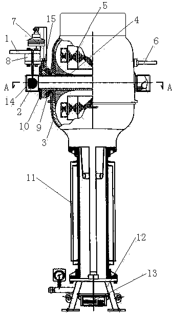
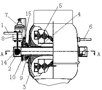
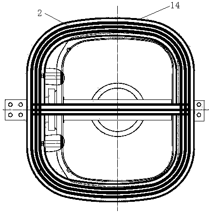
[0014] Refer to attached figure 1 , attached figure 2 , attached image 3 , an outer winding current transformer of the present invention consists of a primary conductive bar 1, a primary winding 2, a housing 3, a conductive tube 4, a secondary winding 5, a secondary conductive bar 6, an overvoltage protector 7, and an insulating terminal 8. Inner insulating plate 9, outer insulating plate 10, bushing 11, base 12, secondary terminal 13, protective cover 14, conductive seat 15, bushing 11 is set on base 12, and the bottom of base 12 is provided with The secondary connection terminal 13 is provided with a casing 3 on the casing 11, and a secondary winding 5 is provided in the inner cavity of the casing 3. The conductive tube 4 passes through the secondary winding 5, and the primary conductive bar 1 passes through the lead wire and the primary winding 5. The windings 2 are connected; a protective cover 14 is provided on the outside of the housing 3, and the primary winding 2 i...


PUM


Abstract

The invention relates to an outer-winding type current transformer used in the electric power industry. The outer-winding type current transformer is composed of a primary conducting bar, a primary winding, a shell, a conducting tube, a secondary winding, a secondary conducting bar, an overvoltage protector, an insulation terminal, an inner insulation plate, an outer insulation plate, a protective cover, a conducting base and the like. A sleeve is arranged on a base, the secondary winding is arranged in an inner cavity of the shell, the primary conducting bar is connected with the primary winding through a lead, the protective cover is arranged on the outer side of the shell, the primary winding penetrates through the conducting tube to be arranged in the protective cover, and various grades of coil taps of the primary winding are respectively connected with the secondary conducting bar. Due to the fact that multiple turns of primary winding coils are arranged in the conducting tube in the secondary winding in a penetrated mode, the current with the low current ratio is increased, and the current output range is expanded; due to the arrangement of the overvoltage protector, devices of the current transformer can be protected; due to the fact that the primary winding penetrates through the conducting tube to be evenly distributed in the protective cover outside the shell, the winding accuracy is high.

Description

technical field [0001] The invention relates to a transformer used in the electric power industry, in particular to an outer winding current transformer. Background technique [0002] After retrieving relevant patent documents, an outer winding current transformer with the same structure as the present invention has not been retrieved yet. Due to its structure, the existing current transformers are generally only suitable for occasions with large current ratios. With the continuous development of technology and the continuous increase of digital circuit detection equipment, when using large current ratio current transformers for detection equipment, it is necessary to The current can be used in the detection circuit only after the voltage transformation process, which brings great inconvenience to the use. my country's patent application number is: 201010573001.7, titled: "A Multi-turn Inverted Current Transformer" discloses a multi-turn inverted current transformer, especi...

Claims


Application Information

Patent Timeline
IPC IPC(8): H01F38/30H01F27/29H01F27/02H01F27/30H01F27/40
Inventor 杨红斌赵凯凯付旭明刘红葛乃军王靖川
Owner JIANGSU SIYUAN HERTZ TRANSFORMER
Learn More