Eureka AIR delivers breakthrough ideas for toughest innovation challenges, trusted by R&D personnel around the world.

Current transformer polarity test rod

A current transformer and polarity testing technology, which is applied in the field of electric power system, can solve problems such as unreliable connection between the test rod and the two poles of the current transformer, which affects the smooth progress of the test work, and reduces the work safety factor, so as to improve work safety. coefficient, simple structure, and the effect of reducing work difficulty

Inactive Publication Date: 2014-05-21
广西桂网电力试验有限公司
View PDF3 Cites 2 Cited by
  • Summary
  • Abstract
  • Description
  • Claims
  • Application Information

AI Technical Summary

Problems solved by technology

In the actual test, due to the unreliable connection between the test rod and the two poles of the current transformer, disconnection accidents often occur, which affects the smooth progress of the test work
In addition, with the increase of the voltage level, the distance between the conductive part and the ground also increases. work efficiency

Method used


Image

  • Current transformer polarity test rod
  • Current transformer polarity test rod
  • Current transformer polarity test rod

Examples


Embodiment 1

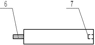
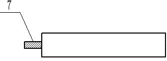
[0021] A current transformer polarity test rod, which includes a wire hook 1, an intermediate connecting insulating rod 4 and a test tail rod 5, wherein the intermediate connecting insulating rod 4 is formed by splicing two hollow insulating rods with a fixed structure . One end of the hollow insulating rod is provided with a groove 7, and the other end is provided with a metal connector 6; the fixed connection structure between two hollow insulating rods is installed on the metal connector 6 connected to the hollow insulating rod Formed in the groove 7 on the hollow insulating rod. The top end of the intermediate connecting insulating rod 4 formed by splicing hollow insulating rods is connected with the wire hook 1, and its bottom end is connected with the test tail rod 5 by a fixed structure. The connecting end of the test tail bar 5 is provided with a metal connector 6; the fixed connection structure between the test tail bar 5 and the intermediate connecting insulating ro...

Embodiment 2

[0024] A current transformer polarity test rod, which includes a wire hook 1, an intermediate connecting insulating rod 4 and a test tail rod 5, wherein the intermediate connecting insulating rod 4 is formed by splicing four hollow insulating rods with a fixed structure . One end of the hollow insulating rod is provided with a groove 7, and the other end is provided with a metal connector 6; the fixed connection structure between every two hollow insulating rods is installed on the metal connector 6 on the hollow insulating rod. Formed in the groove 7 on the hollow insulating rod. The top end of the intermediate connecting insulating rod 4 formed by splicing hollow insulating rods is connected with the wire hook 1, and its bottom end is connected with the test tail rod 5 by a fixed structure. The connecting end of the test tail bar 5 is provided with a metal connector 6; the fixed connection structure between the test tail bar 5 and the intermediate connecting insulating rod ...


PUM


Abstract

The invention discloses a current transformer polarity test rod comprising a wire hook, a middle connecting insulating rod and a test tail rod, wherein the top end of the middle connecting insulating rod is connected with the wire hook, and the bottom end of the middle connecting insulating rod is connected with the test tail rod by virtue of a fixed structure; sawteeth are arranged on the inwards bent curved surface of the wire hook, and an elastic fastener is arranged at the inlet of the wire hook and at the top end of the middle connecting insulating rod; a wire suspending locking seat is arranged on the wire hook, and a direct-current power supply circuit is arranged in the test tail rod. The middle connecting insulating rod is formed by jointing more than two hollow insulating rods by virtue of a fixed structure. According to the invention, the test rod is reliably connected with the outgoing lines of the two poles of the current transformer, and the use length of the test rod can be adjusted, and therefore, the working difficulty is reduced, the working efficiency is improved, and simultaneously, the working safety coefficient is increased.

Description

technical field [0001] The invention belongs to the technical field of power systems, in particular to a polarity test rod for a current transformer. Background technique [0002] With the continuous development of the power grid, the jurisdiction of the equipment is also increasing, and the polarity test work is also constantly appearing in a large number of work sites. In the power system, the polarity of the current transformer is of great significance to the correct action of the relay protection, the power flow calculation of the power system and the correct measurement of the electric load. The polarity test will be carried out after all other work. [0003] When testing the polarity of the current transformer, it is necessary to use the test rod to hang two wires on the two poles of the current transformer, one end is close to the busbar side, and the other end is close to the line side. The swing direction of the meter can be used to judge whether the secondary wir...

Claims


Application Information

Patent Timeline
Patent Type & Authority Applications(China)
IPC IPC(8): G01R1/02G01R31/06
Inventor 钟文谢伟山麦艳红罗小霞
Owner 广西桂网电力试验有限公司
Why Eureka
Eureka Blog
Learn More