


Quick Research
Generate reliable direction feasibility study reports for your R&D in just a few steps.

Technical Q&A
Discover and master advanced knowledge NOW. Basics, ideas, possibilities, all at once.

Find Solutions
As an expert in R&D theories, this can generate solutions to your technical problems instantly.

Evaluate Feasibility
Analyze your overall solution with one click, know your potential R&D risks in advance.

Monitor Landscape
Get weekly tech updates, stay abreast of the latest tech innovations and key insights.
Measuring device and measuring method for element torsion and position parameters
A technology for measuring devices and components, which is applied in the testing of measuring devices, mechanical components, and testing of machine/structural components, etc., can solve the problems of increasing measurement costs, increasing workload, and inability to read data, and achieves light weight. , the effect of small impact and low cost
- Summary
- Abstract
- Description
- Claims
- Application Information
AI Technical Summary
Problems solved by technology
Method used
Image

Examples
Embodiment 1
[0020] This embodiment is described by taking the measurement of the torsion and position parameters of the main cable of the suspension bridge as an example.
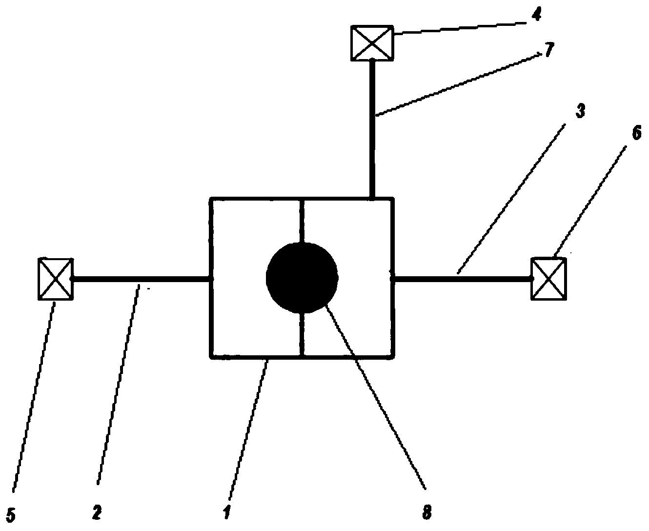
[0021] The measuring device used for component torsion and position parameters provided by the invention is shown in image 3 , including a fixed base 1, and three reflective prism sheets (ie light reflectors) 5, 6, 7 connected to the fixed base through rods 2, 3, 4; The three light reflectors connected to the fixing base are on the same plane as the measured section of the measured element 8 .
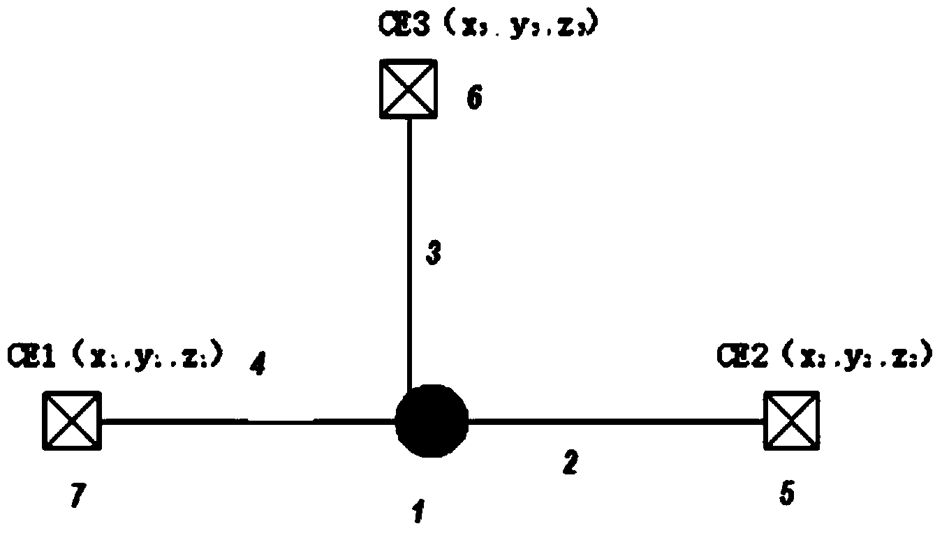
[0022] use figure 1 The shown "orthogonal mode" arranges three hat fins with prism sheets, and the observation points are CE1, CE2 and CE3 respectively.
[0023] The specific implementation is as follows:
[0024] (1) Selection and processing of the fixing seat: Select the fixing seat form of the measuring point reflection device and the installation mode of the hat fin according to the geometric size, material, cross-secti...
Embodiment 2
[0061] This embodiment is described by taking the measurement of the torsion and position parameters of the main cable of the suspension bridge as an example.
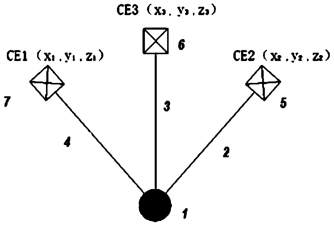
[0062] use figure 2 , 4 The shown "non-orthogonal mode" arranges three hat fins with prism sheets, and the observation point numbers are CE1, CE2, and CE3, respectively.
[0063] Embodiment is identical with embodiment 1.
[0064] In the case of using the "non-orthogonal mode" to arrange the hat fins, the coordinates of the center position of the cross-section of the main cable and the measured values of the torsion angle are calculated according to formula (2) and formula (3), respectively.
[0065] Data processing method and calculation formula
[0066] Let the X-axis of the coordinate system be the horizontal direction of the bridge, and the side along the tension direction of the suspender is the positive direction; the Y-axis is the longitudinal direction of the bridge; the Z-axis is the vertical direction o...
Embodiment 3
[0087] Test effect of the present invention and economic benefit test comparison result
[0088] 1 Comparison of test effects of the present invention
[0089] In the model test research of a self-anchored suspension bridge with a space cable surface, the measurement of the spatial position and torsion angle of the main cable uses an inclinometer and the product of the present invention to compare the test results. The section was tested, and 5 cross-sectional positions of the main cable were selected for comparison. The method was: both the product of the present invention and the inclinometer were installed at the same cross-sectional position of the main cable. Taking the measurement results of the inclinometer as a comparison reference, by calculating the relative error between the angle value (increment relative to the initial value) measured by the method of the present invention and the angle value (increment relative to the initial value) measured by the inclinometer ...
PUM
 Abstract
Description
Claims
Application Information
 - R&D Engineer
- R&D Manager
- IP Professional
- Industry Leading Data Capabilities
- Powerful AI technology
- Patent DNA Extraction
Browse by: Latest US Patents, China's latest patents, Technical Efficacy Thesaurus, Application Domain, Technology Topic, Popular Technical Reports.
© 2024 PatSnap. All rights reserved.Legal|Privacy policy|Modern Slavery Act Transparency Statement|Sitemap|About US| Contact US: help@patsnap.com