Two-way side pull vacuum gate valve

A technology of vacuum insert plate and valve plate, which is applied in the direction of sliding valve, valve details, valve device, etc., can solve the problems of inability to isolate and seal large-sized valve ports, poor valve plate sealing, inconvenient maintenance, etc., and achieve a high degree of equipment automation. , The effect of uniform force and high pressure

Active Publication Date: 2015-12-09
SHENYANG CHINANORTH VACUUM TECH CO LTD
View PDF6 Cites 0 Cited by
  • Summary
  • Abstract
  • Description
  • Claims
  • Application Information

AI Technical Summary

Problems solved by technology

The existing vacuum continuous furnace plug valve has the following problems: 1. There is only one valve plate in the valve box, which is sealed on one side; 2. The valve plate is locked by a cylinder, the locking force is small, and the sealing performance of the valve plate is poor, so it cannot be used for large sizes. The valve port is isolated and sealed; 3. The rigid cooling water inlet and outlet pipe has no mandatory linear protection outside the valve body, and the flexible metal bellows is not used inside the valve box to solve the relative movement between the valve plate and the rigid cooling water inlet and outlet pipe assembly; 4. The valve plate Up and down movable structure, inconvenient maintenance

Method used


Image

  • Two-way side pull vacuum gate valve
  • Two-way side pull vacuum gate valve
  • Two-way side pull vacuum gate valve

Examples


Embodiment Construction

[0020] The present invention will be further described below in conjunction with the accompanying drawings and embodiments.

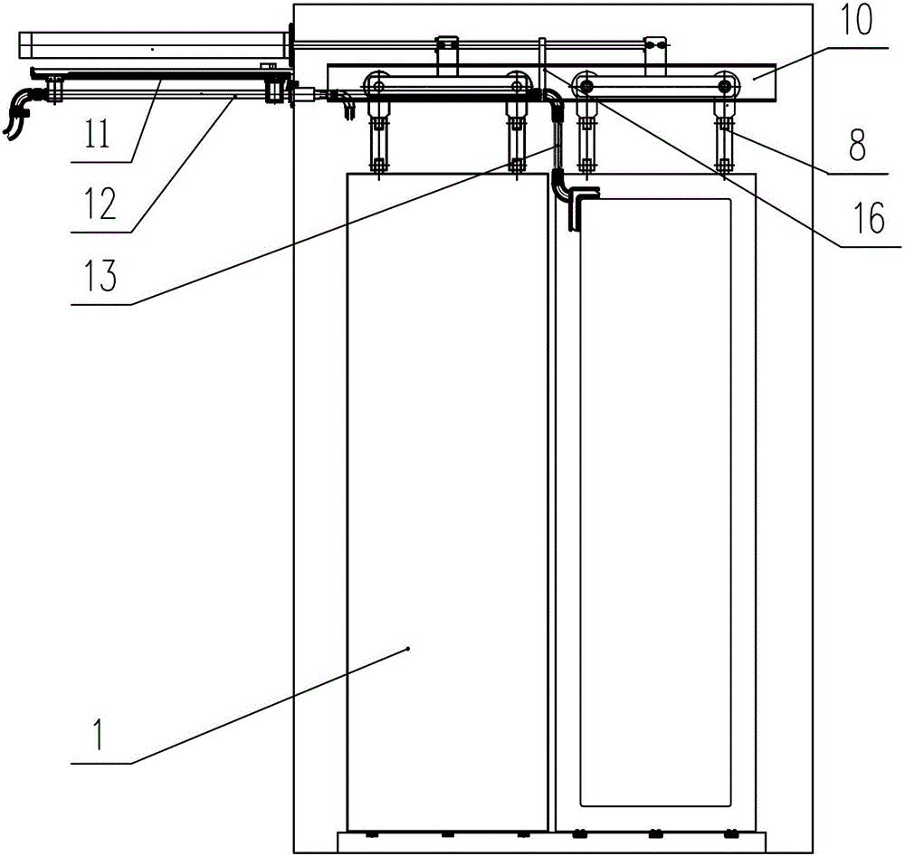
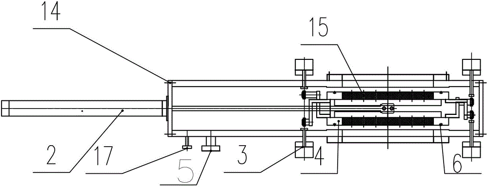
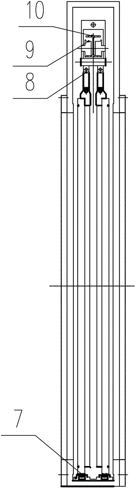
[0021] The invention provides a two-way side-pull vacuum gate valve, such as Figure 1~3 As shown, it includes a valve box body 1, a cylinder 2, a gas-liquid booster cylinder 3, a valve plate 4, a valve plate traveling device, and a rigid cooling water inlet and outlet pipe assembly 12, wherein the corresponding sides of the valve box body 1 are respectively provided with blind The upper part of the blind flange 14 on one side is provided with the cylinder 2 and the rigid cooling water inlet and outlet pipe assembly 12; the valve box body 1 is provided with a valve plate 4 parallel to the other two sides, and the valve plate 4 is hung on the valve plate by the valve plate walking device In the upper part of the valve box body, the valve plate traveling device is rigidly connected with the cylinder head of the external cylinder 2, and the bottom of the v...


PUM


Abstract

The invention provides a vertical large-dimension rectangular-valve-opening two-way lateral pulling vacuum gate valve for neodymium iron boron rare earth permanent magnetic alloy vacuum multi-chamber continuous sintering furnaces and hydrogen desorption furnaces. The two-way lateral pulling vacuum gate valve comprises a valve box body, an air cylinder, an air and hydraulic pressure boosting cylinder, a valve plate, a valve plate walking device and a rigid cooling water inlet and outlet pipe assembly, wherein blind flanges are respectively arranged at the two corresponding sides of the valve box body, the air cylinder and the rigid cooling water inlet and outlet pipe assembly are arranged at the outer upper part of the blind flange arranged at one side, a water cooling valve plate parallel to the other two sides of the box body is arranged in the valve box body, the valve plate is suspended to walk at the inner upper part of the valve box body through the valve plate walking device, the valve plate walking device is in rigid connection with the cylinder rod cylinder head part of the external air cylinder, the bottom of the valve plate is provided with a pulley guide rail, and a water cooling pipe joint of the valve plate is flexibly connected with a rigid cooling water inlet and outlet pipe element. The two-way lateral pulling vacuum gate valve is applied to the ultra-large-dimension rectangular valve opening, so the multi-scale continuous sintering furnaces and the hydrogen desorption furnaces in large-scale production can realize the safe and effective operation, the automation degree is high, the product performance is good, the equipment investment is reduced, and the energy consumption is greatly reduced.

Description

technical field [0001] The invention relates to the field of powder metallurgy equipment, and relates to a vacuum multi-chamber continuous sintering furnace of neodymium-iron-boron rare earth permanent magnet alloy and a vertical large-size rectangular valve port two-way side-pull vacuum plug-in valve for a hydrogen breaking furnace. Background technique [0002] Powder metallurgy vacuum sintering furnaces and hydrogen-breaking furnaces are large energy consumers in industrial production. With the urgent demand for energy-saving and emission reduction in industrialized production in the world, multi-chamber continuous vacuum sintering furnaces and hydrogen-breaking furnaces with good energy-saving effects and consistent product performance are presented. With great advantages, the gate valve plays a vital role in the reliability of multi-chamber continuous sintering furnace and hydrogen breaking furnace. [0003] In 2006, the FHH-120 multi-chamber continuous vacuum heat trea...

Claims


Application Information

Patent Timeline
Patent Type & Authority Patents(China)
IPC IPC(8): F16K3/02F16K31/12F16K49/00F16L59/16
CPCF16K3/0254F16K3/029F16K31/12F16K49/00
Inventor 陈晓东孙宝玉
Owner SHENYANG CHINANORTH VACUUM TECH CO LTD
Why Eureka
Try Eureka