Controlled Flow Sleeve

A sliding sleeve and flow technology, which is applied in wellbore/well components, earthwork drilling, sealing/packing, etc., can solve the problems such as the inability to change the flow rate of the sliding sleeve and the inability to close the through-hole of the sliding sleeve, and achieve a reasonable structure, Easy-to-use effects

Active Publication Date: 2017-01-11
BC P INC CHINA NAT PETROLEUM CORP +1
View PDF7 Cites 0 Cited by
  • Summary
  • Abstract
  • Description
  • Claims
  • Application Information

AI Technical Summary

Problems solved by technology

[0003] The utility model provides a controllable flow sliding sleeve, which overcomes the shortcomings of the above-mentioned prior art, and can effectively solve the problem of the existing sliding sleeve in the actual use process. There are problems that the flow rate entering the sliding sleeve cannot be changed and the through hole on the sliding sleeve cannot be closed

Method used


Image

  • Controlled Flow Sleeve
  • Controlled Flow Sleeve

Examples


Embodiment Construction

[0017] The utility model is not limited by the following examples, and the specific implementation manner can be determined according to the technical scheme of the utility model and actual conditions.

[0018] In this utility model, for the convenience of description, the description of the relative positional relationship of each component is described according to the layout method of Fig. The relationship is determined according to the layout direction of Figure 1 of the specification.

[0019] Below in conjunction with embodiment and accompanying drawing, the utility model is further described:

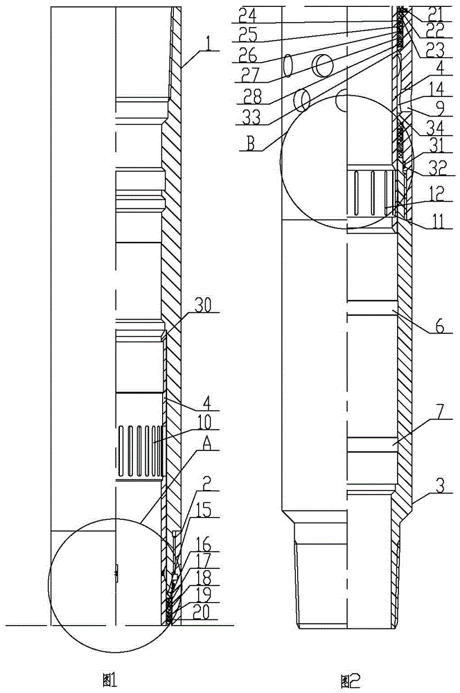
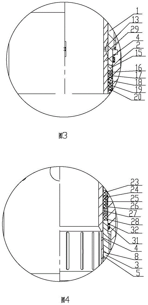
[0020] As shown in accompanying drawings 1 to 4, the controllable flow sliding sleeve includes an upper joint 1, a double female joint 2, a lower joint 3 and an inner sliding sleeve 4, and the outer side of the lower part of the upper joint 1 is fixed together with the upper part of the double female joint 2, The lower part of the double female joint 2 is fixed together with the...


PUM


Abstract

The invention relates to the technical field of sliding sleeves for well-completion practice, and discloses a flow-controllable sliding sleeve. The flow-controllable sliding sleeve comprises an upper joint, a double-female joint, a lower joint and an inner sliding sleeve. The outer side of the lower portion of the upper joint is fixed together with the upper portion of the double-female joint, the lower portion of the double-female joint is fixed together with the outer side of the upper portion of the lower joint, a first annular groove, a second annular groove and a third annular groove are sequentially formed in the inner side of the lower joint at intervals from top to bottom, and the inner sliding sleeve is sequentially arranged on the inner side of the upper joint, the inner side of the double-female joint and the inner side of the lower joint from top to bottom in a sleeved mode. The flow-controllable sliding sleeve is reasonable and compact in structure and convenient to use, in the well-completion practice process, a communication channel between the inner sliding sleeve and an oil gas layer can be closed through the arrangement of an upper strip-shaped through hole, a radial through hole, a radial outer through hole, the first annular groove, the second annular groove and the third annular groove, and meanwhile the flow of oil gas entering the flow-controllable sliding sleeve can be changed according to oil recovery requirements.

Description

technical field [0001] The utility model relates to the technical field of sliding sleeves for well completion operations, which is a controllable flow sliding sleeve. Background technique [0002] Well completion is an important technical means to connect drilling and oil production operations. At the same time, well completion is an extremely risky downhole operation. Therefore, the success of well completion will directly affect the success or failure of a well. Especially with the continuous deepening of exploration of unconventional oil and gas fields such as shale gas and tight oil, people's research on the development of such oil and gas reservoirs is also constantly strengthening. For the development of this type of oil and gas reservoirs, fracturing well completion is also an indispensable technical means. Regardless of the well completion operation of conventional oil and gas reservoirs or the completion of oil and gas wells in unconventional oil and gas reservoir...

Claims


Application Information

Patent Timeline
Patent Type & Authority Patents(China)
IPC IPC(8): E21B34/14
Inventor 宋朝晖李晓军穆总结江波李富强柯学
Owner BC P INC CHINA NAT PETROLEUM CORP
Why Eureka
Try Eureka