
Inverted drilling machine

An inverted drilling machine technology, applied to boring machine/drilling machine components, positioning devices, boring/drilling, etc., can solve the problems of unresolved accuracy, wear and tear of the end of the drill pipe, and reduce the processing accuracy Reduce, protect the drill pipe and workpiece, reduce the effect of production cost

Inactive Publication Date: 2014-05-21
滕天阳
View PDF5 Cites 7 Cited by
  • Summary
  • Abstract
  • Description
  • Claims
  • Application Information

AI Technical Summary

Problems solved by technology

[0003] The drilling machine with inverted layout has certain limitations, that is, the structure of the fixture parts is simple, and usually the same or similar fixture components are used as the drilling machine with the upright layout, which cannot overcome the adverse effects of the vibration generated when processing the workpiece, and cannot Guarantee the indexing accuracy of the workpiece processing, and it does not solve the problem of strengthening the positioning accuracy of the workpiece under the premise of easy loading and unloading. It is also because of the aforementioned defects that the tool drill blade is prone to collapse during processing, which is the so-called At this time, the overall uncontrollability causes the workpiece to directly contact the end of the drill pipe. The end of the high-speed rotating drill pipe will be worn or even destroyed, and the workpiece will also be scrapped, posing a safety hazard.

Method used


Image

  • Inverted drilling machine
  • Inverted drilling machine
  • Inverted drilling machine

Examples


Embodiment Construction

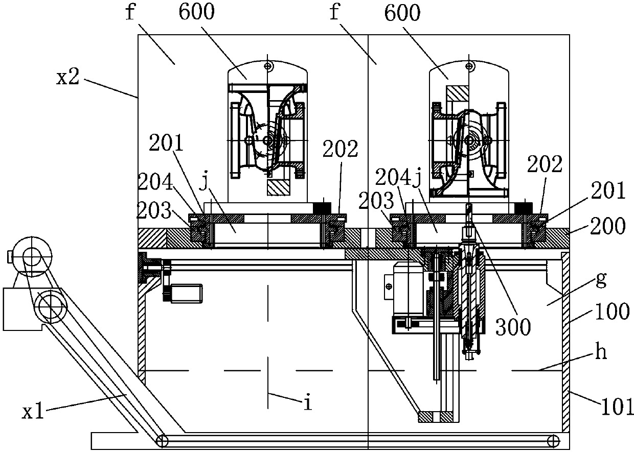
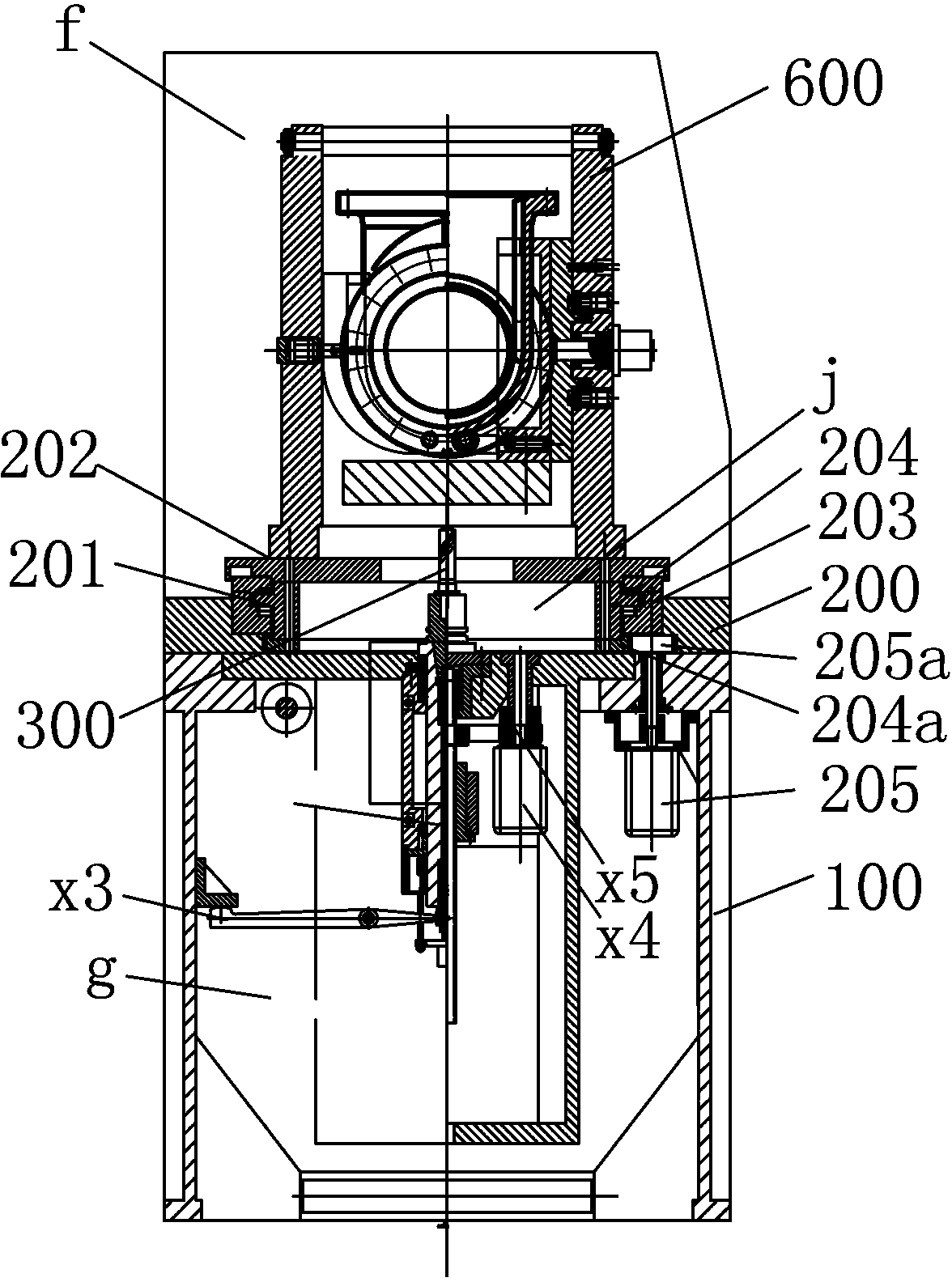
[0019] Figure 1 to Figure 2 Represents the overall structure of the embodiment of the inverted drilling machine of the present invention, including the bed 100 and the workbench 200, the workbench 200 is provided with a station part 201 and a drill part 300, and the drill part 300 is located below the station part 201, meaning The drill bit loaded on the drill part 300 will cut the workpiece from bottom to top, and the station part 201 is provided with a station 202 for loading the workpiece 9, a fixture part 600 for indexing processing of the workpiece 9 and a workpiece space above the station 202 f, the fixture part 600 is located in the workpiece space f, the workpiece 9 is loaded in the fixture part 600 , and the workpiece 9 and the fixture part 600 are loaded in the work station 202 as a whole.

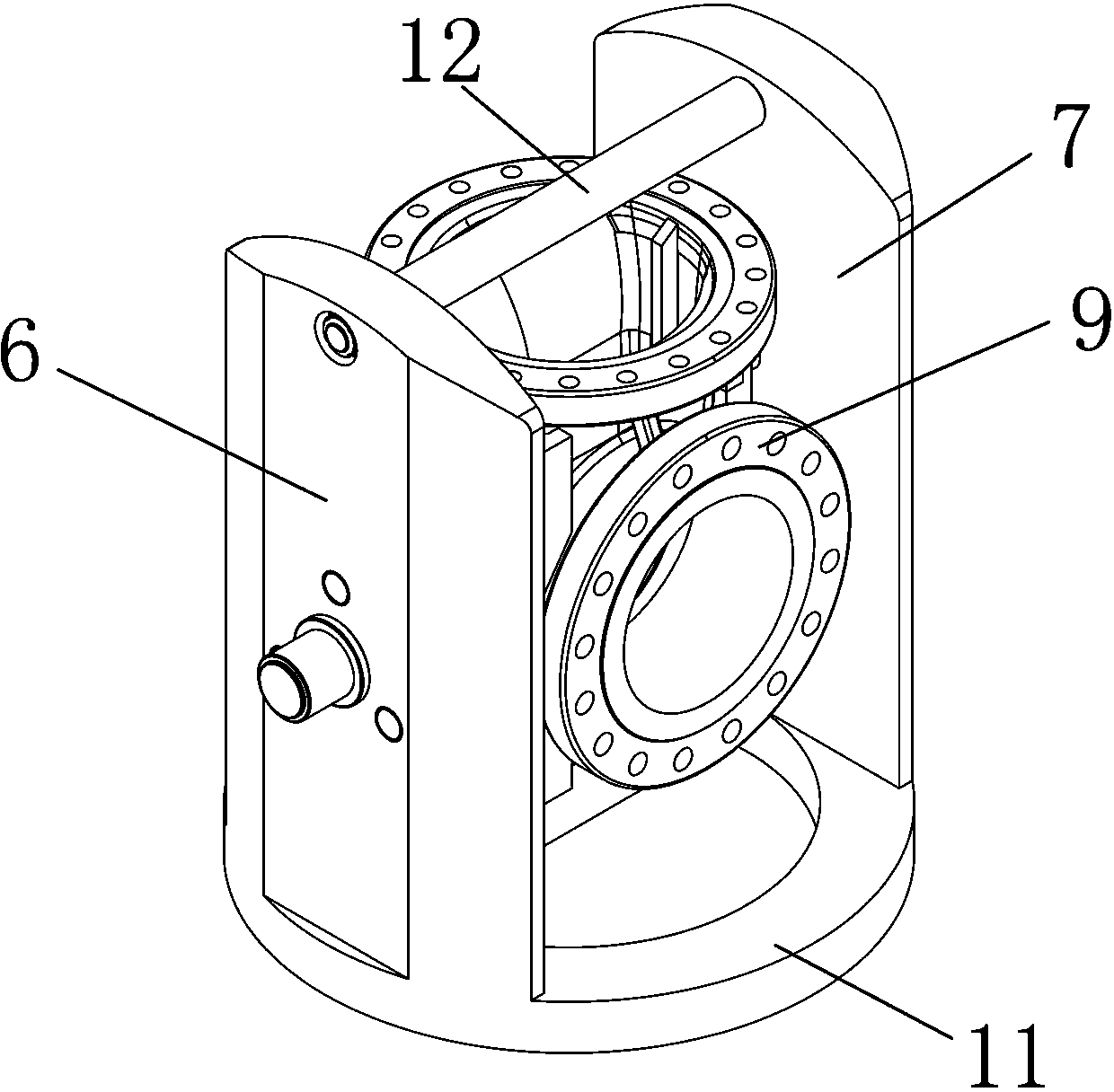
[0020] Figure 3 to Figure 7 The fixture part 600 in the embodiment is shown, and the fixture part 600 includes a fixture body space 8 for accommodating a workpiece 9, left and...


PUM


Abstract

The invention relates to an inverted drilling machine which has the characteristics of easiness for assembling and disassembling and accuracy and reliability for indexing and comprises a bed and a working table. The working table is provided with a station part and a drilling tool part; the station part is provided with a station for loading a workpiece, a fixture part for carrying out indexing machining on the workpiece and a workpiece space positioned above the station; the fixture part comprises a fixture body space for accommodating the workpiece and left and right side fixture bodies respectively positioned at two opposite sides of the fixture body space; the left and right side fixture bodies are fixedly arranged on the working table; the left side fixture body is provided with a positioning hydraulic cylinder and a positioning plate; the right side fixture body is provided with a connecting block, a positioning block, a swing hydraulic cylinder, a locking hydraulic lock, a moving gear ring and a static gear ring; the drilling tool part comprises a drill stem; the drill stem is provided with a drill stem end face and a cutting blade; the cutting blade is provided with an edge part which is in contact with the workpiece; the edge part rotates to form a cutting mapped circle which is axially mapped; an abutting element is arranged on the drill stem end face in the range of the cutting mapped circle; the lowermost point of the edge part is higher than the highermost point of the abutting element; the highmost point of the abutting element is higher than the highermost point of the drill stem end face.

Description

technical field [0001] The present invention relates to drill presses, and more particularly to drill presses with an inverted layout. Background technique [0002] A traditional drilling machine will include a tool carrier and a workpiece carrier. The tool is loaded on the tool carrier, and the workpiece to be processed is loaded on the workpiece carrier. The tool carrier can be used to drive the tool to achieve various movements, and the workpiece carrier It is used to drive the workpiece to achieve various movements, and then realize the mutual cooperation between the tool and the workpiece, so that the workpiece can obtain the required geometric shape, dimensional accuracy and surface quality. Drilling machines will include a bed for placement on the ground and a workbench above the bed. Correctly placing the bed ensures the levelness of the workbench. Drilling machines in the prior art can be roughly divided into tool loads and workpiece loads. Above, the upright type ...

Claims


Application Information

Patent Timeline
IPC IPC(8): B23B39/00B23Q3/08B23B47/00
CPCB23B39/00B23Q3/082
Inventor 滕天阳
Owner 滕天阳
Learn More