Power adapter and capacitor protection device thereof

A power converter and capacitor protection technology, which is applied to emergency protection circuit devices, electrical components, irreversible AC power input to DC power output, etc., can solve the problem of increased installation space, damage to surge absorbers, and power converters. Component damage and other issues can be reduced to reduce frequency and improve safety and satisfaction

Active Publication Date: 2014-05-14
QISDA SUZHOU +1
View PDF5 Cites 4 Cited by
  • Summary
  • Abstract
  • Description
  • Claims
  • Application Information

AI Technical Summary

Problems solved by technology

[0004] (1) Use high-voltage capacitors with higher withstand voltage specifications: Although this approach helps to improve the above-mentioned burst phenomenon, it also leads to a substantial increase in component costs
[0005] (2) Two high-voltage capacitors in series: Although this method can double the withstand voltage, it is theoretically calculated that four high-voltage capacitors need to be connected in parallel so as not to affect the normal functional operation. need to increase
[0007] However, since the surge absorber needs to withstand quite high energy when it starts, and it can be known from the formula △W=△V*△I*△t: this energy △W is proportional to the action time △t of the surge current △I, assuming The action time △t of the surge current △I is quite short (1-10 microseconds), and the surge absorber can easily absorb it. Once the action time △t is longer, the surge absorber may not be able to withstand too high energy △W and the damage caused a short circuit, and also caused damage to other related circuit components, such as a bridge rectifier damaged and a short circuit or a fuse damaged and an open circuit
Although this method can avoid the risk of high-voltage capacitor bursting, it also causes damage to the components of the power converter, requiring the machine to be repaired, which also causes great inconvenience to users

Method used


Image

  • Power adapter and capacitor protection device thereof
  • Power adapter and capacitor protection device thereof
  • Power adapter and capacitor protection device thereof

Examples


Embodiment Construction

[0027] In order to have a further understanding of the purpose, structure, features, and functions of the present invention, the following detailed descriptions are provided in conjunction with the embodiments.

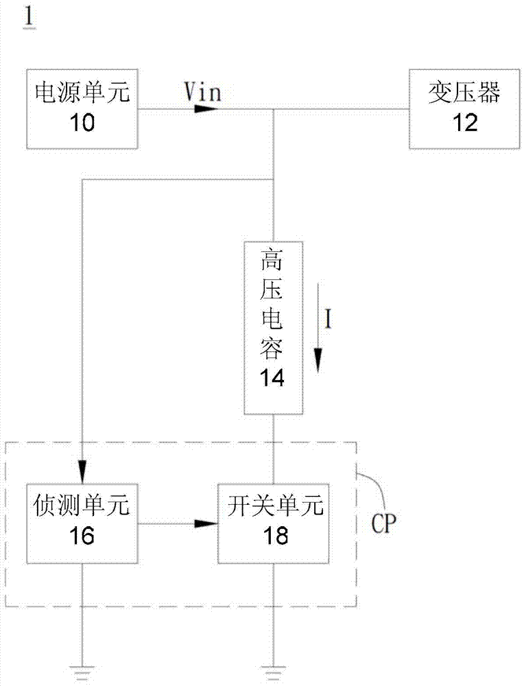
[0028] A preferred embodiment of the present invention is a power converter (power board). In practical applications, the power converter is used in the AC / DC power conversion of the liquid crystal display device to convert the AC mains power into multiple sets of DC voltages and provide the drivers, speakers and backlight modules of the liquid crystal display device. Electricity, but not limited to. Please refer to figure 1 , figure 1 It is a functional block diagram of a power converter according to an embodiment of the present invention.

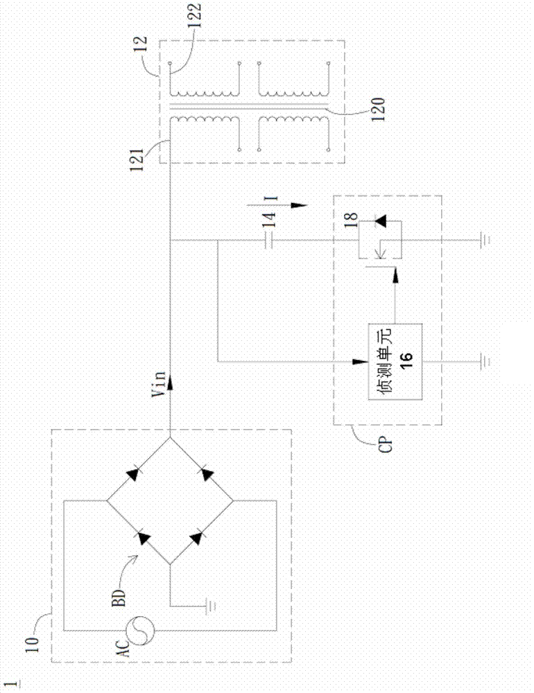
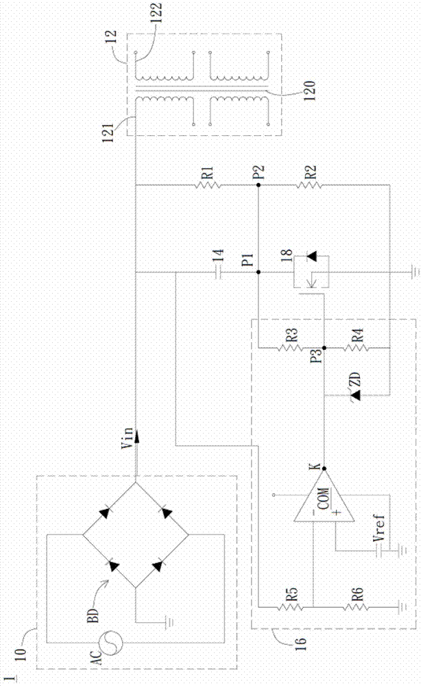
[0029] Such as figure 1 As shown, the power converter 1 includes a power unit 10 , a transformer 12 , a high voltage capacitor 14 and a capacitor protection device CP. The capacitor protection device CP includes a detection ...


PUM


Abstract

The invention discloses a power adapter which comprises a capacitor and a capacitor protection device. The capacitor protection device comprises a switching unit and a detection unit. The switching unit is connected between one end of the capacitor and a grounding end in a coupled mode and the detection unit is respectively connected with the other end of the capacitor and the switching unit in a coupled mode and used for detecting the input voltage of the other end of the capacitor and judging whether the input voltage is larger than a critical voltage value or not. If yes, the detection unit outputs a control signal to the switching unit to turn off the switching unit, and therefore the voltage drop borne by the capacitor is smaller than the input voltage.

Description

technical field [0001] The invention relates to the protection of high-voltage capacitors, in particular to a power converter and a capacitor protection device thereof. Background technique [0002] Generally speaking, the power converter (power board) is used in the AC / DC power conversion of the liquid crystal display device to convert the AC power into multiple sets of DC voltage and provide the core board, speaker and backlight of the LCD TV. power supply. Since the high-voltage capacitor (bulk capacitor) in the power converter has a volatile electrolyte with a low ignition point, once the input voltage exceeds the withstand voltage of the high-voltage capacitor, the volatile electrolyte with a low ignition point is likely to burst and cause combustion. Danger. [0003] In order to solve the above problems, there are three traditional approaches: [0004] (1) Use high-voltage capacitors with higher withstand voltage specifications: Although this approach helps to impro...

Claims


Application Information

Patent Timeline
Patent Type & Authority Applications(China)
IPC IPC(8): H02H7/16H02M7/02
Inventor 王博文阙锦盛
Owner QISDA SUZHOU
Why Eureka
Try Eureka