Method for applying M sequence to phase encoding system imaging radar pulse compression

A technology of pulse compression and phase encoding, applied in the field of radar imaging, can solve the problems that the sidelobe suppression cannot reach the ideal state and the optimization effect is limited

Inactive Publication Date: 2014-05-14
SHANGHAI INST OF TECHNICAL PHYSICS - CHINESE ACAD OF SCI
View PDF1 Cites 8 Cited by
  • Summary
  • Abstract
  • Description
  • Claims
  • Application Information

AI Technical Summary

Problems solved by technology

However, the optimization effect is limited, and the suppression of side lobes cannot reach the ideal state

Method used


Image

  • Method for applying M sequence to phase encoding system imaging radar pulse compression
  • Method for applying M sequence to phase encoding system imaging radar pulse compression
  • Method for applying M sequence to phase encoding system imaging radar pulse compression

Examples


Embodiment Construction

[0034] The application of M-sequence to phase-encoded synthetic aperture lidar imaging requires the following steps:

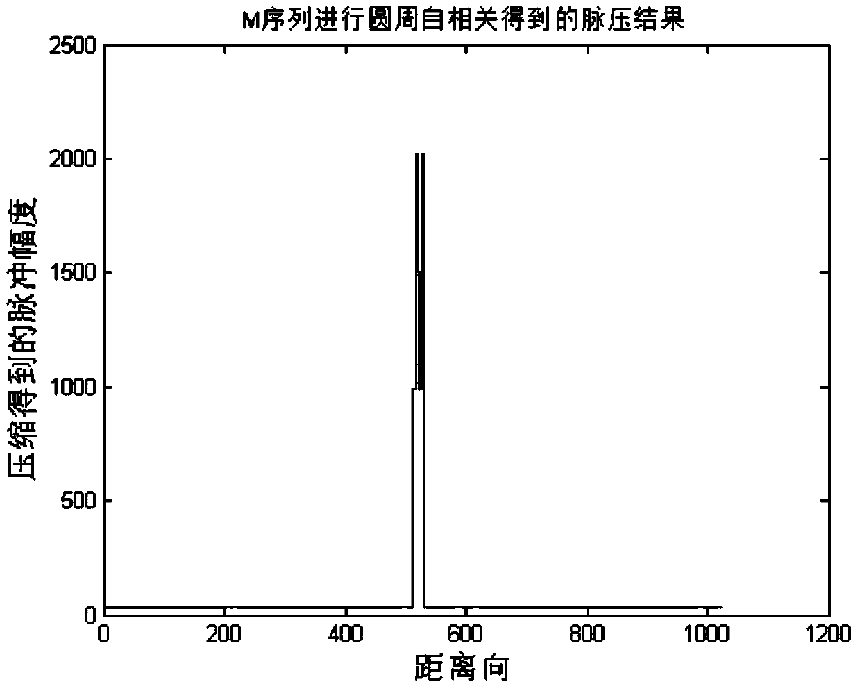
[0035] 1) Use a single-length M-sequence to phase-modulate the laser waveform, and the sequence encoding length P is determined according to engineering needs. Modulating waveforms are emitted in pulses.

[0036] 2) Acquisition of the echo signal from the target reflection along the azimuth direction: the laser echo is collected by the balance detector and AD, and the superimposed phase encoding information in the echo pulse is collected as a matrix S(r,n). R represents the scale of data collected upwards in distance, and N represents the scale of data in upward direction in azimuth.

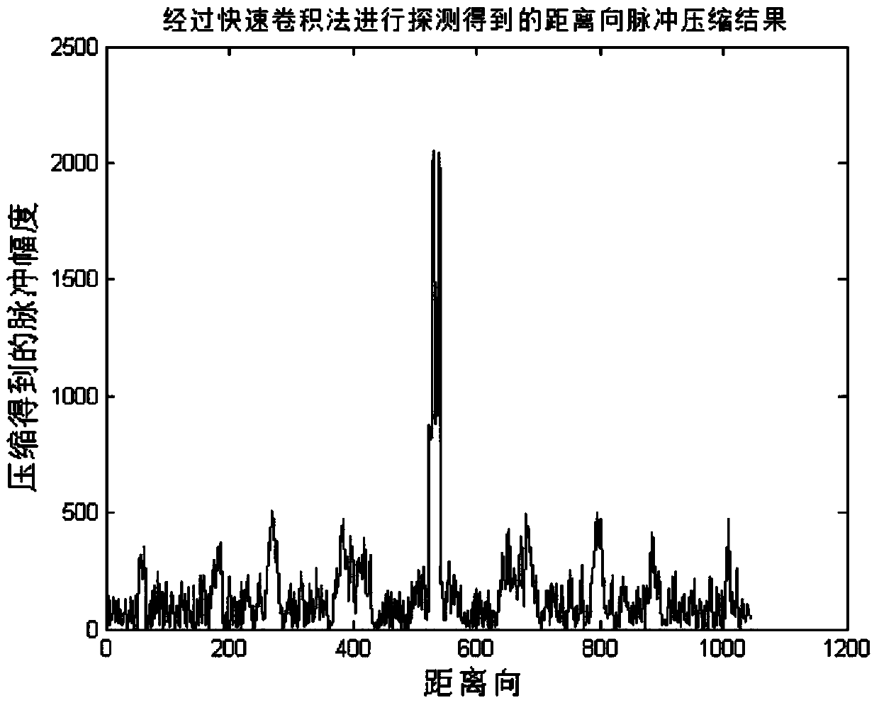
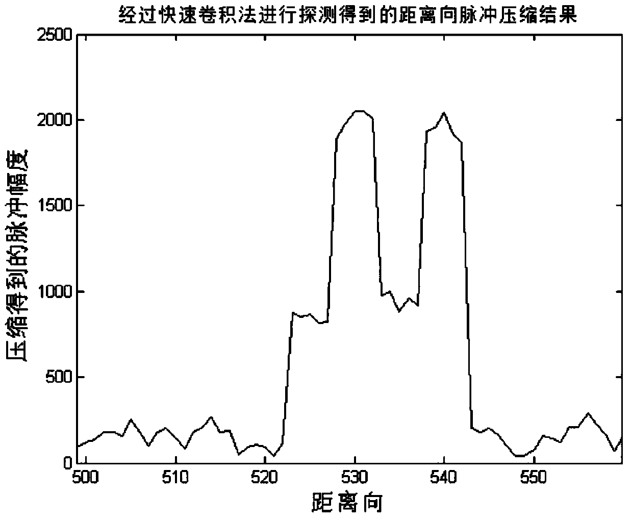
[0037] 3) Use formula (3) to construct the matched filter matrix H(p,r), and perform the operation y(p,n)=H(p,r)*S(r,n).

[0038] 4) The obtained y(p,n) is the data obtained by pulse compression in the distance direction, and then the pulse compression processing in the azimut...


PUM


Abstract

The invention discloses a method for applying an M sequence to phase encoding system imaging radar pulse compression. The method is applied to a laser synthetic aperture radar imaging system. With the method adopted, the problem of imaging quality reduction and existence of virtual images which are caused by excessive sidelobe which is further caused by a situation that a traditional pulse compression system adopts a fast convolution method to perform pulse compression, can be solved. According to the method of the invention, phase codes are the M sequence, and the algorithm of pulse compression is a periodic convolution method. The method is characterized in that a matrix which is used for the pulse compression and is constructed in a manner that the M sequence is prolonged and is subjected to shifting operation so as to form the matrix is used so as to match the design of a filter. With the method adopted, sidelobe suppression can be realized under the premise that the complexity of the algorithm is not increased, and the sidelobe can be suppressed to be 1 / P under the condition that the length of code elements is P.

Description

technical field [0001] The invention relates to radar imaging technology, in particular to a pulse compression method for imaging radar with M sequence applied to phase coding system. Background technique [0002] According to the theory of lidar, in the case of limited power, to achieve long-distance detection, a large pulse duration is required, and high detection accuracy requires a high detection bandwidth. The simple pulse duration and bandwidth product is close to In 1, the time width and bandwidth are related to each other, and the time width and bandwidth cannot be increased at the same time. That is to say, for a simple laser pulse of constant wavelength, there is a contradiction between the maximum operating distance and the distance resolution. In order to solve this contradiction, the transmitted signal must adopt a complex signal form with a large time-width bandwidth. [0003] The Synthetic Aperture Lidar (SAL) system requires a high resolution due to its lon...

Claims


Application Information

Patent Timeline
Patent Type & Authority Applications(China)
IPC IPC(8): G01S7/487
CPCG01S17/90
Inventor 舒嵘张鸿翼李飞
Owner SHANGHAI INST OF TECHNICAL PHYSICS - CHINESE ACAD OF SCI
Why Eureka
Try Eureka