
Geotechnical thermal response test system

A test system, cold and heat technology, applied in the direction of material thermal conductivity, material thermal development, etc., can solve the problems of long test time, large volume, complex system, etc., and achieve the effect of shortening test time, compact structure and high control precision.

Active Publication Date: 2017-01-18
上海建科节能技术有限公司
View PDF5 Cites 0 Cited by
  • Summary
  • Abstract
  • Description
  • Claims
  • Application Information

AI Technical Summary

Problems solved by technology

[0004] 1) The traditional geotechnical thermal property test system of ground source heat pump generally uses electric heating device or heat pump unit as the heating and cooling module of the system. The former can only perform thermal response test, although the latter can perform cold and thermal response test, It has problems such as large volume and complex system;
[0005] 2) The traditional ground source heat pump rock and soil thermal physical property testing system is generally aimed at a single test well. After starting the test, it is necessary to run the system without turning on the heating and cooling modules to measure the initial temperature of the rock and soil, and then turn on the heating, The refrigeration module is tested. When the system is stable, the average heat transfer per meter of the test well is calculated by the collected flow rate and inlet and outlet water temperature values. The relative test time is relatively long, and the heat transfer capacity of different rock and soil layers cannot be calculated. and the influence between adjacent test wells are analyzed

Method used


Image

  • Geotechnical thermal response test system

Examples


Embodiment Construction

[0021] The embodiments of the present invention will be described in further detail below in conjunction with the accompanying drawings, but the present embodiments are not intended to limit the present invention, and any similar structures and similar changes of the present invention should be included in the protection scope of the present invention.

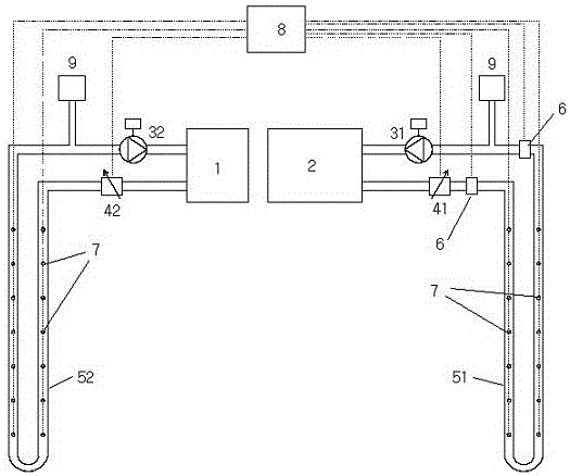
[0022] Such as figure 1 As shown, a rock and soil thermal response test system provided by the embodiment of the present invention is characterized in that it includes a data acquisition device 8, a constant temperature water bath device 2, a circulating water tank 1, a first circulating water pump 31, and a second circulating water pump 32 , and two test wells;

[0023] Each of the two test wells is buried with a buried pipe, wherein the buried pipe in one test well is the first buried pipe 51, and the buried pipe in the other test well is the second buried pipe 52;

[0024] The water outlet of the constant temperature water...


PUM


Abstract

The invention discloses a rock soil cold and hot response testing system, and relates to the technical field of ground source heat pumps, aiming to solve the technical problems of testing time shortening and the rock soil heat exchange capability calculation. The system comprises a data collecting device, a constant-temperature water bath device, a circulation water tank, a first circulation water pump, a second circulation water pump and two testing wells, wherein a buried pipe is embedded in each of the two testing wells respectively, wherein one buried pipe is a first buried pipe, and the other buried pipe is a second buried pipe; a water outlet of the constant-temperature water bath device is connected with a water inlet of the constant-temperature water bath device by the first buried pipe and the first circulation water pump; pipe openings in two ends of the first buried pipe are respectively provided with a pipe opening temperature sensor; each vertical pipe section of two buried pipes is respectively provided with a plurality of pipe internal temperature sensors; the water outlet of the circulation water tank is connected to a water inlet of the circulation water tank by the second buried pipe and the second circulation water pump. The system disclosed by the invention is suitable for rock soil cold and hot response testing.

Description

technical field [0001] The invention relates to ground source heat pump technology, in particular to a technology of a rock-soil cold-heat response test system. Background technique [0002] The ground source heat pump system uses the shallow geothermal resources on the earth's surface as the cold and heat source. By inputting a small amount of high-grade energy, the energy can be transferred from the low-temperature heat source to the high-temperature heat source. It has a series of advantages such as stable operation, energy saving and environmental protection, and low maintenance costs. , has been more and more applied in today's society where energy is increasingly tight. The core basis for the design of ground source heat pump systems is the heat transfer capacity of rock and soil. A large number of engineering practices have proved that the heat transfer capacity of rock and soil in different regions will be very different. Therefore, it is very important to test the t...

Claims


Application Information

Patent Timeline
Patent Type & Authority Patents(China)
IPC IPC(8): G01N25/20G01N25/18
Inventor 杜佳军陈煜赵彦杰邢立亮赵宏恺
Owner 上海建科节能技术有限公司
Learn More