
Mobile terminal power distribution method in heterogeneous wireless network cooperative communication system

A heterogeneous wireless network and cooperative communication technology, which is applied in the field of mobile terminal power allocation based on particle swarm algorithm, and can solve problems such as optimization without considering the power consumption performance of mobile terminals.

Inactive Publication Date: 2014-05-07
SOUTH CHINA UNIV OF TECH
View PDF2 Cites 12 Cited by
  • Summary
  • Abstract
  • Description
  • Claims
  • Application Information

AI Technical Summary

Problems solved by technology

The publication number is CN101588627A, and the publication date is November 25, 2009. The invention patent "Method for Optimum Joint Power Distribution of Source and Relay Nodes in Cooperative Communication" considers that the sum of the power of the source node and the relay node must be constant. Under the premise of , the water injection algorithm is used to allocate power to the source and relay nodes, but this invention is also aimed at a single homogeneous network, and only maximizes the system capacity as the optimization goal, without considering the power consumption performance of the mobile terminal (source node) Optimization

Method used


Image

  • Mobile terminal power distribution method in heterogeneous wireless network cooperative communication system
  • Mobile terminal power distribution method in heterogeneous wireless network cooperative communication system
  • Mobile terminal power distribution method in heterogeneous wireless network cooperative communication system

Examples


Embodiment

[0041] The implementation process of the present invention mainly includes two parts, access control (selecting the relay node to be accessed) and allocating the transmission power of the mobile terminal.

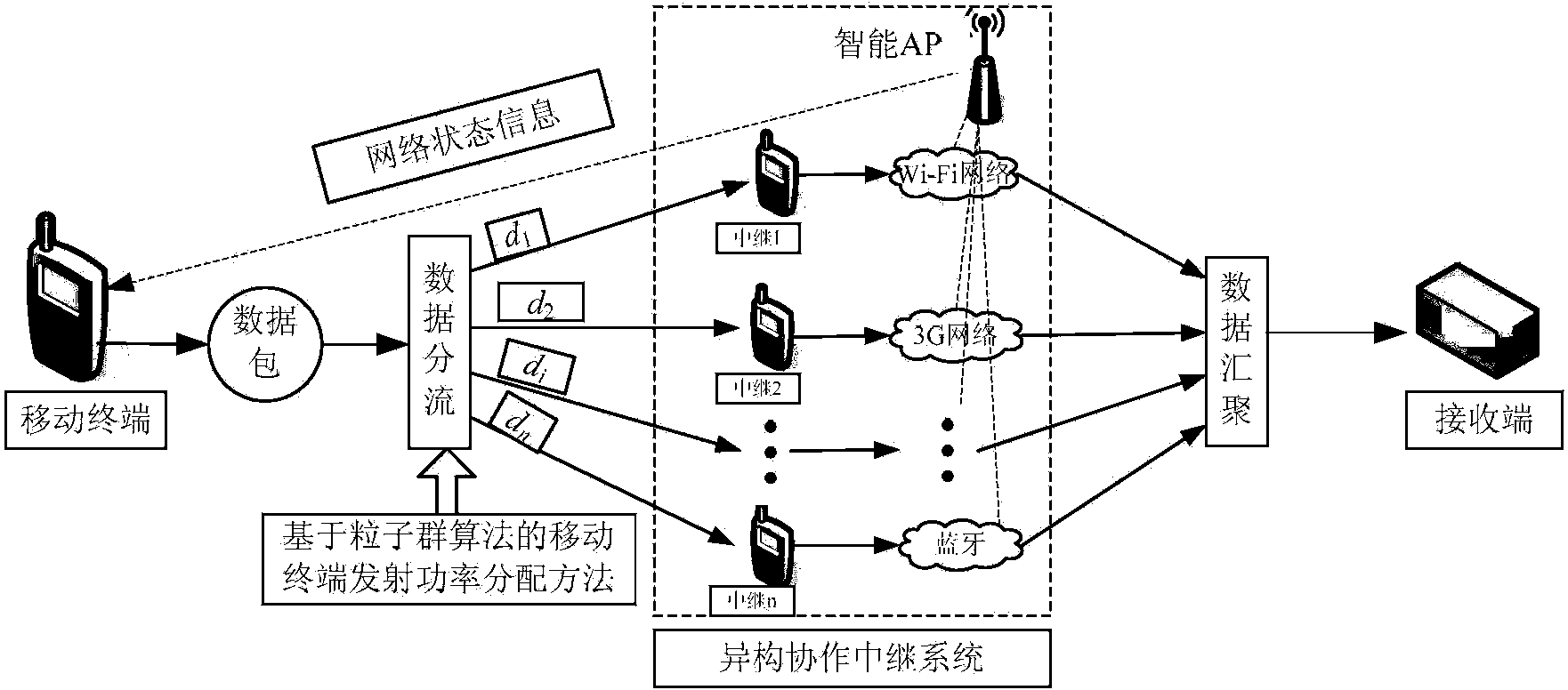
[0042] In this example, figure 1 Shown is the mobile terminal transmission power allocation flow chart, figure 2 Shown is the mobile terminal transmission power allocation and data transmission mode in the heterogeneous wireless network cooperative communication system.

[0043] The implementation steps of access control in this embodiment are as follows:

[0044] Step 1, such as figure 2 In the heterogeneous wireless network model shown, the intelligent wireless access point (AP) monitors the channel statistical characteristics of each relay link in real time.

[0045] Step 2, figure 2 The shown mobile terminal requests the intelligent AP to obtain the channel statistical characteristics of each relay link, and the intelligent AP sends the channel statistical charac...


PUM


Abstract

The invention discloses a mobile terminal power distribution method in a heterogeneous wireless network cooperative communication system. The method comprises the following steps: the step 1 in which the mobile terminal is used to detect that L relay nodes which can be used to provide the cooperative communication service exist; the step 2 in which a particle population representing the power distribution scheme is generated; the step 3 in which a fitness function of the power distribution scheme is defined; the step 4 in which initial fitness values of particles are calculated; the step 5 in which particle individual extremum value and global extremum value initialization is performed; the step 6 in which a new generation of particle population is generated; the step 7 in which the fitness value of each particle in the new generation of particle population is recalculated; the step 8 in which particles are selected to undergo mutation and the mutated particles are judged whether to be legal; the step 9 in which the particle individual extremum value and global extremum value are updated; and the step 10 in which the global extremum value is selected as the transmitting power distribution scheme of the mobile terminal. According to the invention, the particle swarm algorithm is used to distribute the transmitting power of the mobile terminal in the heterogeneous cooperative communication system, and at the same time, the receiving end signal-to-noise ratio and the power consumption performance of the mobile terminal can be optimized.

Description

technical field [0001] The invention belongs to the technical field of wireless communication, and in particular relates to a mobile terminal power distribution method based on a particle swarm algorithm in a heterogeneous wireless network cooperative communication system. Background technique [0002] At present, there are many heterogeneous networks in the wireless communication environment, such as GSM, CDMA, Wi-Fi, UWB, Bluetooth, etc. However, these network technologies have their own characteristics, each heterogeneous network works independently, and a mobile terminal can only access one network at a time, which cannot make full use of idle network resources. Heterogeneous wireless network cooperative communication technology can realize the mutual integration and cooperation between multiple heterogeneous networks, so that mobile terminals can use multiple heterogeneous networks to transmit data at the same time, make full use of idle network resources, and optimize ...

Claims


Application Information

Patent Timeline
Patent Type & Authority Applications(China)
IPC IPC(8): H04W52/24H04W52/46
Inventor 冯义志林炳辉田坤张军
Owner SOUTH CHINA UNIV OF TECH
Learn More