
Push switch structure far away from hot spot

A switch structure and switch technology, applied in the direction of electric switches, electrical components, circuits, etc., can solve the problems of increased overall cost, inability to effectively reduce the volume, and dislike of users, and achieve the effect of saving space

Inactive Publication Date: 2014-05-07
SOLTEAM ELECTRONICS
View PDF4 Cites 1 Cited by
  • Summary
  • Abstract
  • Description
  • Claims
  • Application Information

AI Technical Summary

Problems solved by technology

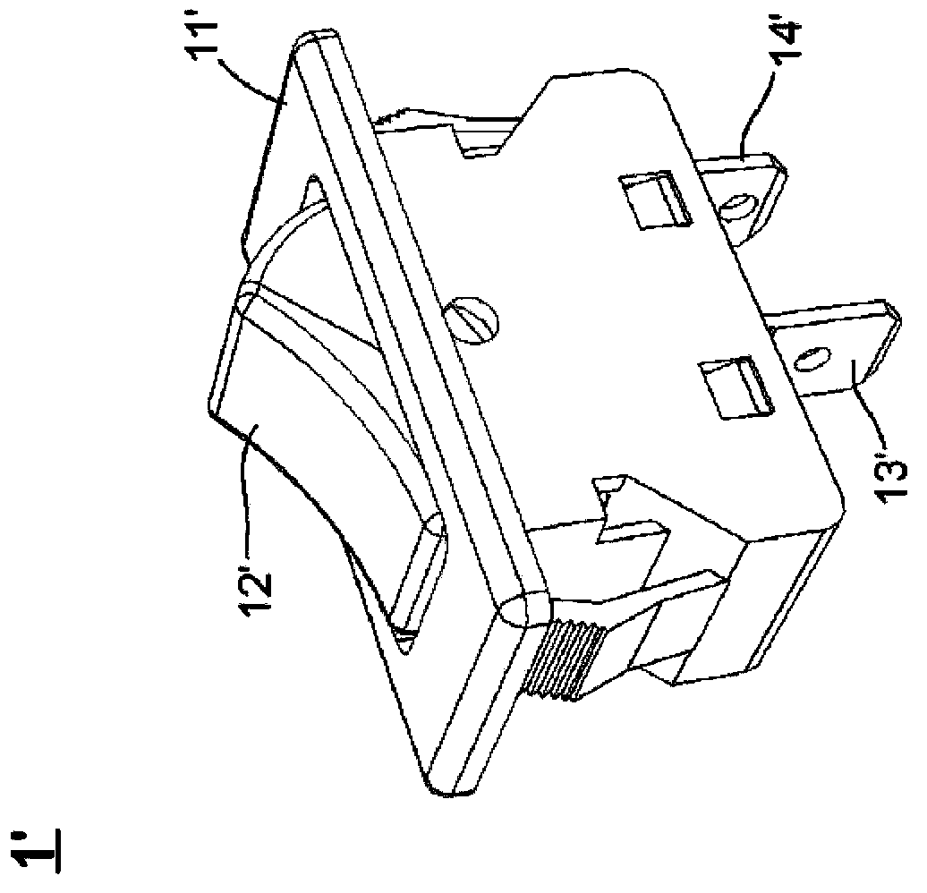
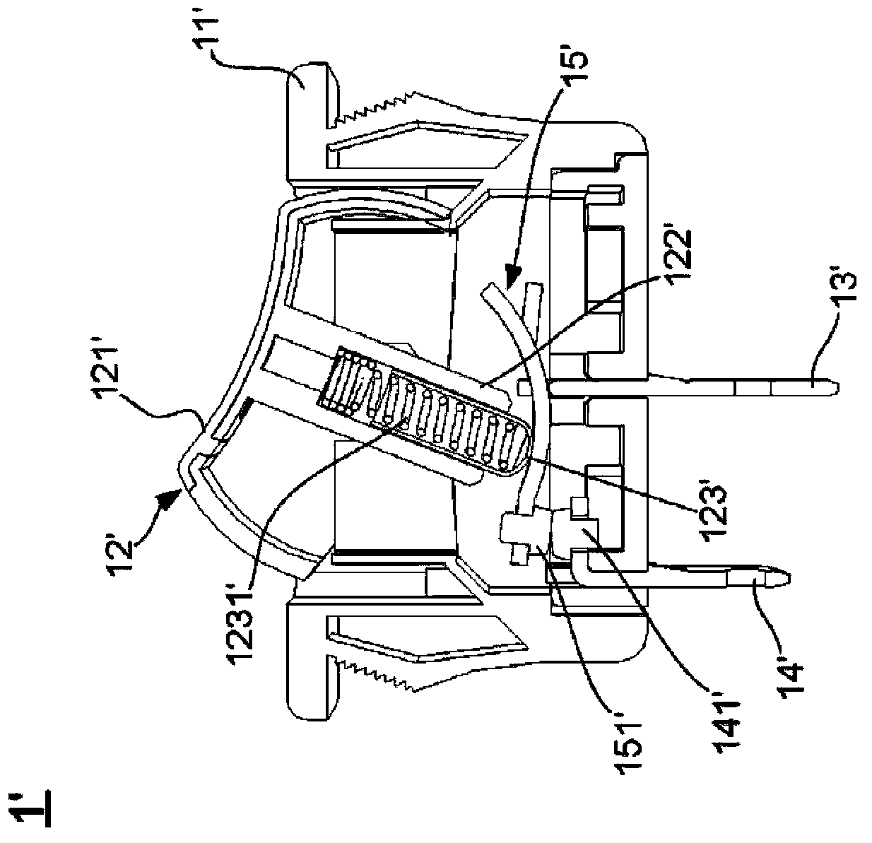
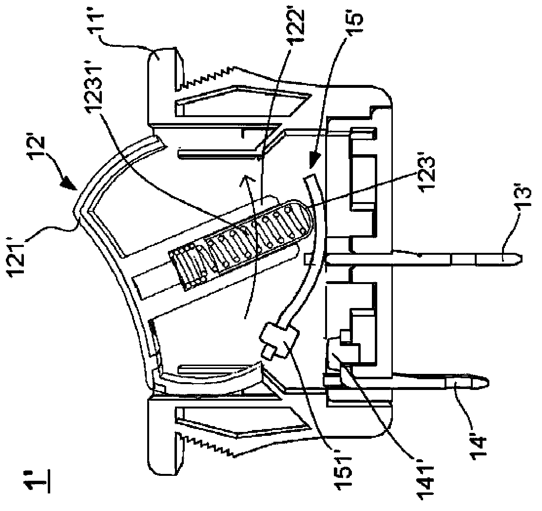
[0007] (2) Metal is used as the material of the shrapnel bar 123 ′, although the existing conventional push-type switch 1 ′ can be used on a larger switch rating (Switch rating), but it does make the existing conventional push-type switch 1 ′ 1' overall cost increase
[0008] (3) Based on the above point (2), and the structure of the shrapnel resisting rod 123' and the spring 1231' also makes the inside of the housing 11' of the conventional push switch 1' require a larger accommodation space, Only enough to accommodate the rocking part 122' of the push-type switch 12', the shrapnel bar 123', the spring 1231', and the switch shrapnel 15', so that the overall volume of the conventional push-type switch 1' cannot be effectively reduced
[0009] (4) Following the above point (3), in addition, more importantly, although the structure of the shrapnel resisting rod 123' and the spring 1231' can increase the contact force between the switch shrapnel 15' and the second terminal 14', on the contrary As a result, the user cannot easily toggle the push-type switch 12', making the user gradually dislike the conventional push-type switch 1'
[0015] (B) After long-term use, the first elastic piece 114" and the second elastic piece 115" will gradually lose their elasticity, so that the user must exert more force to stabilize the contact between the contacts; The first shrapnel 114" and the second shrapnel 115" are easily affected by temperature. The above-mentioned reasons make the micro switch module 1" and its switch mechanism group 11" unable to be used on a larger switch rating (Switch rating)
[0016] This shows that above-mentioned existing switchgear obviously still has inconvenience and defect in structure and use, and urgently needs to be further improved
In order to solve the above-mentioned problems, the relevant manufacturers have tried their best to find a solution, but for a long time no suitable design has been developed, and the general product has no suitable structure to solve the above-mentioned problems. This is obviously the relevant industry. Urgent problem

Method used


Image

  • Push switch structure far away from hot spot
  • Push switch structure far away from hot spot
  • Push switch structure far away from hot spot

Examples


Embodiment Construction

[0082] In order to further explain the technical means and effects of the present invention to achieve the intended purpose of the invention, the specific implementation and structure of a push switch structure with hot spots away from the present invention will be described below in conjunction with the accompanying drawings and preferred embodiments. , features and their effects are described in detail below.

[0083] read on Figure 7 and Figure 8 , is a perspective view and an exploded view of the structure of the push switch away from the hot spot of the present invention. Such as Figure 7 and Figure 8 As shown, the push switch structure 1 of the present invention, which is away from hot spots, includes: a support terminal 11, a compression spring 12, a switch shrapnel 13, an electrical terminal 14, a switch slide bar group 15, a slide bar return spring 16, and a return spring fixing seat 17 ; Wherein, one end of the compression spring 12 is connected to the suppor...


PUM


Abstract

The present invention relates to a push switch structure far away from a hot spot. The push switch structure far away from the hot spot mainly comprises a supporting terminal, a compression spring, a switch spring leaf, an electrical terminal and a switch slide bar set. According to the present invention, the compression spring, the switch spring leaf and a switching member of the switch slide bar set are connected in a similar stacking manner, so that the overall occupation space of the push switch structure can be saved effectively. In addition, with the special structure design of the supporting terminal, the compression spring, the switch spring leaf, the electrical terminal and the switch slide bar set, when two contacts are contacted tightly, a certain distance exists between the switching member of the switch slide bar set and the contact point of the two contacts, so that the switching member is far away from the hot spot formed by the contact point, and accordingly, the switching member is not melted even though the push switch structure is used for a long time.

Description

technical field [0001] The invention relates to a switch structure applied to a push switch, in particular to a push switch structure of a hot spot away type. Background technique [0002] A switch is an indispensable mechanism for electrical equipment and electronic products. For example, refrigerators, TVs, extension cords, computers, and video games must be powered on or off through switches; among them, push-type switches are the most common. A type of switch. [0003] see figure 1 and figure 2 , is a perspective view and a side sectional view of a conventional push-type switch. Such as figure 1 and figure 2 As shown, the conventional push-type switch 1' mainly includes: a housing 11', a push-type switch element 12', a first terminal 13', a second terminal 14', and a switch spring 15'; wherein, the push-type switch 12', the first terminal 13', the second terminal 14', and the switch spring 15' are placed in the housing 11', and one end of the first terminal 13' a...

Claims


Application Information

Patent Timeline
Patent Type & Authority Applications(China)
IPC IPC(8): H01H13/12H01H13/20H01H13/26
Inventor 何应松黄桢宏陈昶男韦宏儒赖辰威薛道隆
Owner SOLTEAM ELECTRONICS
Learn More