Eureka AIR delivers breakthrough ideas for toughest innovation challenges, trusted by R&D personnel around the world.

Support fine-tuning device applied to pre lens optical axis alignment

A technology of fine-tuning device and front mirror, which is applied in installation, optics, optical components, etc., can solve the problems of inconvenient movement, inability to adjust the height direction, high cost, etc., and achieve simple structure, convenient adjustment and operation, and a small number of parts Effect

Active Publication Date: 2014-05-07
西安应用光学研究所
View PDF8 Cites 25 Cited by
  • Summary
  • Abstract
  • Description
  • Claims
  • Application Information

AI Technical Summary

Problems solved by technology

Ordinary fine-tuning devices have a complex structure, high manufacturing costs, and it is difficult to adapt the angle and height. The combination temporarily built with ordinary devices is huge in size, unstable in connection, and inconvenient to move
Therefore, ordinary simple devices are difficult to solve the problems of convenient installation, alignment adjustment and safety of photoelectric systems during calibration and testing
[0003] Chinese patent 201120399627 discloses "an angle fine-tuning device". This device mainly uses a worm gear and a worm pair as an angle adjustment mechanism. Due to the use of a worm gear, the structure is complicated, the manufacturing is difficult, the cost is high, and it can only be wound around one Axis for angle adjustment, not two-dimensional angle adjustment
Chinese patent 200910041514 discloses a "manual fine-tuning mechanism". This device adopts a spherical pair structure, which can realize the adjustment of the rotation angle, but its function is relatively single, it does not have a lifting function, and the height direction cannot be adjusted; in addition, because it has three rotating degrees of freedom, so too many degrees of freedom make the adjustment process complicated and difficult to align quickly and accurately

Method used


Image

  • Support fine-tuning device applied to pre lens optical axis alignment
  • Support fine-tuning device applied to pre lens optical axis alignment
  • Support fine-tuning device applied to pre lens optical axis alignment

Examples


Embodiment Construction

[0018] The present invention will be further described in detail below in conjunction with the accompanying drawings and preferred embodiments.

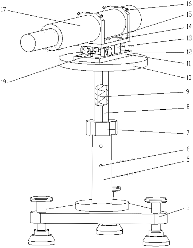
[0019] Such as figure 1 As shown, the support fine adjustment device provided by the preferred embodiment of the present invention includes an adjustment platform 1, a lifting assembly and an angle fine adjustment assembly.

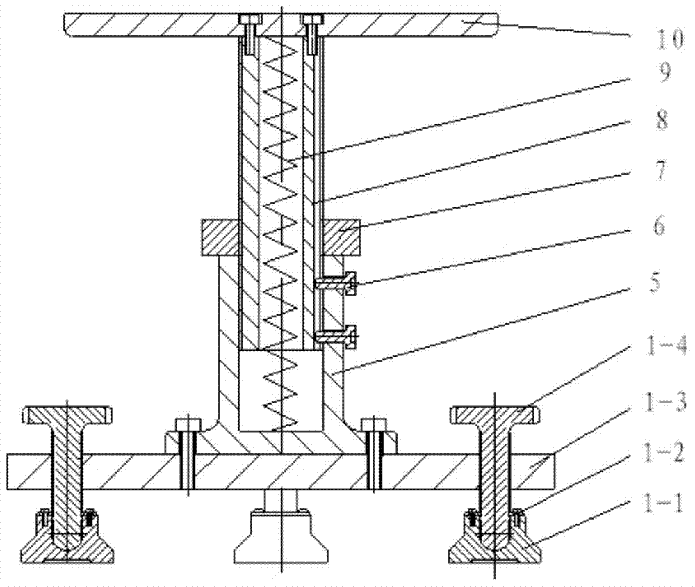
[0020] Such as figure 2 As shown, the adjusting platform 1 has a triangular platen 1-3 and three adjusting angle screws. The middle part of the triangular platen 1-3 is provided with a set of screw holes, and the three top corners are respectively provided with a threaded hole; the three adjusting angle screws are composed of three supporting seats 1-1, three cards 1-2, and three adjusting screws. Composed of 1-4 handwheels. Adjusting hand wheel 1-4 is a T-shaped structure, with anti-slip straight knurling on the raised part of the upper end, threaded on the lower end and connected with the threaded hole of ...


PUM


Abstract

The invention discloses a support fine-tuning device applied to pre lens optical axis alignment. The device is formed by fixedly connecting a leveling platform, a lifting component and an angle fine-tuning component from bottom to top. The leveling platform uses a three point leveling principle to realize rapid leveling. The lifting component uses a nut screw mechanism with limiting and a tension spring to realize smooth and continuous lifting. A pipe seat in the angle fine-tuning component is fixedly connected with a ball pin. A base is fixedly connected with a ball pin seat. The ball pin and the ball pin seat form a spherical pair. A limiting shaft on the ball pin and a rectangular groove on the base form a sliding pair. When in use, a pre lens is arranged in the pipe seat. By rotating a pitch wheel on the pipe seat, fine-tuning and locking can be carried out on the pitch angle of the pre lens. By rotating an orientation wheel on the base, the pipe seat is pushed to realize fine-tuning and locking of the orientation angle of the pre lens, thus a pre lens optical axis is accurately aligned with a tested product. According to the invention, the problems of support and fine-tuning of the pre lens are solved, and the device has the characteristics of simple structure, convenient erection, small occupied space, convenient adjusting and the like.

Description

technical field [0001] The invention belongs to the field of process devices, and mainly relates to a process device used when the optical axis is aligned, in particular to a supporting fine-tuning process device for adjusting the angle and height when the optical axis of a front mirror is aligned with a product to be tested. Background technique [0002] In optoelectronic systems, it is often required that the optical axis of the system be parallel to the reference. During the optical-mechanical adjustment of the photoelectric system, front mirrors are often used to build various optical paths to adjust and test the optical axis of the system. Due to the different structural dimensions, shapes, and optical paths of various photoelectric systems, at this time, it is necessary to use a fine-tuning device to adjust the angle and height of the front mirror according to the actual position of the photoelectric system under test, so that the optical axis of the front mirror is in...

Claims


Application Information

Patent Timeline
IPC IPC(8): G02B7/00
Inventor 王章利杨海成张云龙张锦亮扈宇姝张燕惠刚阳张伟平王中强左晓舟刘欣
Owner 西安应用光学研究所
Why Eureka
Eureka Blog
Learn More