A jet mixer

A technology of jet water mixer and water mixer, which is applied in jet pumps, machines/engines, lifting valves, etc., which can solve the problems of high user comfort, difficulty in guaranteeing water outlet effect, increased difficulty of use, etc., and achieves a simple operation mode Effect

Active Publication Date: 2016-10-05
GUANGZHOU SEAGULL KITCHEN & BATH PROD
View PDF9 Cites 0 Cited by
  • Summary
  • Abstract
  • Description
  • Claims
  • Application Information

AI Technical Summary

Problems solved by technology

[0007] When the nozzle is rotated, the needle valve and the nozzle move together. During this process, the nozzle and the needle valve do not move relative to each other, so that the cross-sectional area of ​​the cold water outlet remains constant. In this way, when the cross-sectional area of ​​the cold water inlet is smaller than that of the cold water outlet When the cross-sectional area is small, the water pressure of the cold water in the nozzle will be very small, and it is difficult to achieve a good spray effect. In order to ensure a good spray effect, it is necessary to adjust the needle valve at the same time, thereby reducing the cross-sectional area of ​​the cold water outlet, and then requiring Simultaneous adjustment of the needle valve and nozzle increases the difficulty of use, and if the needle valve and nozzle are not adjusted at the same time, it will be difficult to ensure a better water discharge effect and higher use comfort

Method used


Image

  • A jet mixer
  • A jet mixer
  • A jet mixer

Examples


Embodiment 1

[0058] Such as Figure 10 As shown, this embodiment provides a jet water mixer, including a water mixer body A and a jet injection valve B, the water mixer body A has a cold water port A1, a hot water port A2 and a water mixing outlet, the jet The injection valve B has a cold water inlet B1 and a hot water inlet B2, the cold water inlet A1 communicates with the cold water inlet B1, and the hot water inlet A2 communicates with the hot water inlet B2, by adjusting the cold water inlet A1 and the The opening size of the hot water port A2 is used to adjust the amount of cold water and hot water entering the jet injection valve B.

[0059] In this embodiment, the opening size of the cold water port A1 is adjusted through the cold water adjustment switch, and the opening size of the hot water port A2 is adjusted through the hot water adjustment switch. In this embodiment, the cold water adjustment switch It has the same structure as the hot water regulating switch.

[0060] The co...

Embodiment 2

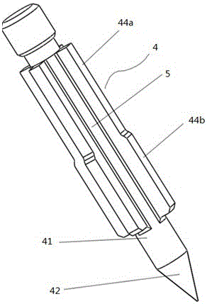
[0087] Such as Figure 7 As shown, this embodiment is an improvement on the basis of the jet mixer provided in embodiment 1, and the main improvement is that the supporting body of the spray needle 4 adopts a different structure. In this embodiment, the support body is an annular support plate 45 arranged on the needle body 41, and a plurality of flow guides for the fluid channel 5 are formed on the surface of the annular support plate 45. Hole 46. The inflow of cold water is unobstructed, and can evenly support the spray needle 4 .

Embodiment 3

[0089] Such as Figure 6 As shown, this embodiment is an improvement on the basis of the jet mixer provided in embodiment 1, and the main improvement is that the supporting body of the spray needle 4 adopts a different structure. In this embodiment, the supporting body is a circular ring 43, and the circular ring 43 is connected to the needle body 41 through a plurality of ribs 40, and the fluid channel 5 is formed between the ribs 40. This arrangement not only ensures smooth inflow of cold water, but also supports the spray needle 4 evenly.


PUM


Abstract

Disclosed is a jet water mixer, comprising a jet spray valve (B). The jet spray valve (B) is provided with a valve body (1), a spray nozzle (3), a spray needle (4) and a water outlet, wherein a cold water inlet (B1) and a hot water inlet (B2) are arranged on the valve body (1); the spray needle (4) is arranged in the spray nozzle (3); an inflow space for cold water (9) and a jet outlet for cold water (32) are formed between the spray nozzle (3) and the spray needle (4); an inflow space for hot water (8) is formed between the spray nozzle (3) and the valve body (1); the cold water inlet (B1) is respectively in communication with a cold water opening (A1) and the inflow space for cold water (9); the hot water inlet (B2) is respectively in communication with a hot water opening (A2) and the inflow space for hot water (8); and when in use, the inflow space for cold water (9), the inflow space for hot water (8) and the jet outlet of cold water (32) can be adjusted by merely adjusting the spray nozzle (3) to make the same move along the axial direction of the jet spray valve (B), thereby realizing a better spray effect in a relatively simple manner of operation.

Description

technical field [0001] The invention relates to a jet liquid mixer, in particular to a jet liquid mixer used in a solar water heater water supply system, and belongs to the technical field of solar water heaters. Background technique [0002] Existing solar water heater mainly comprises pressurized type and non-pressurized type. [0003] The working principle of the pressurized solar water heater is: the tap water enters the water tank and the heat pipe through the control switch, the heat collecting pipe absorbs the solar radiation and transfers the heat energy to the cold water in the heat pipe through the medium, and circulates the water in the water tank. Since the water tank is an overall closed structure, The cold water inlet must be opened during use, and the hot water in the water tank is pushed out with the hydraulic pressure of tap water, so that the hot water flows into the water unit from the water outlet. The water tank with this structure bears the pressure of...

Claims


Application Information

Patent Timeline
Patent Type & Authority Patents(China)
IPC IPC(8): F16K11/22F16K27/00F16K31/58
CPCF16K11/044F16K11/22F16K27/0254F16K27/0263F16K31/508F04F5/10F04F5/463F16K1/123F16K11/04F16K19/006
Inventor 袁训平汤志强
Owner GUANGZHOU SEAGULL KITCHEN & BATH PROD
Why Eureka
Try Eureka