
Electric vehicle motive power assembly

A powertrain and electric vehicle technology, applied in the direction of electric power units, power units, vehicle components, etc., can solve the problems of reduced driving range, high noise, low manufacturing cost, etc., and achieve fast shift response speed and load capacity Strong, long-lasting effect

Inactive Publication Date: 2014-05-07
徐州铭尊机电有限公司
View PDF5 Cites 7 Cited by
  • Summary
  • Abstract
  • Description
  • Claims
  • Application Information

AI Technical Summary

Problems solved by technology

[0002] With the rise of fuel prices and the continuous enhancement of people's awareness of environmental protection, electric vehicles have the characteristics of "zero" emissions. At the same time, the working range of the motor is very wide. Its constant torque at low speed and constant power at high speed are very suitable for vehicle operation. Nowadays, most electric vehicles use fixed speed ratio reducers. Although the transmission method is simple, the manufacturing cost is low, and the maintenance cost is low; this is easy to generate noise, low efficiency, resonance, low energy utilization rate, and in most cases the efficiency is low. Very low area, which wastes precious battery energy and reduces driving range
According to the driving characteristics of electric vehicles, the driving motor should not only provide high instantaneous torque in the constant torque area, but also provide high operating speed in the constant power area to meet the high-speed requirements and acceleration climbing requirements of the vehicle. Under the current technical conditions, it is difficult for electric vehicle drive motors to meet such requirements
[0003] For high-end electric vehicles, clutches and traditional manual transmissions are generally used to change gears. The operation is complicated and the driver's labor intensity is high. It is configured on electric vehicles that emphasize automation and intelligence. In addition, clutches and transmissions will greatly increase the cost of electric vehicles. Not conducive to the miniaturization of electric vehicles

Method used


Image

  • Electric vehicle motive power assembly
  • Electric vehicle motive power assembly
  • Electric vehicle motive power assembly

Examples


Embodiment Construction

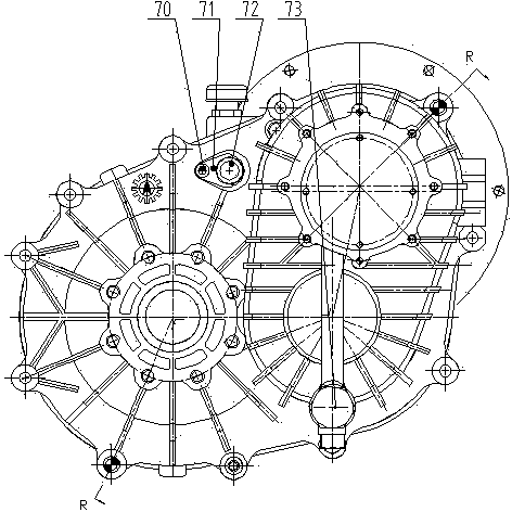
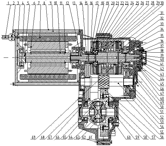
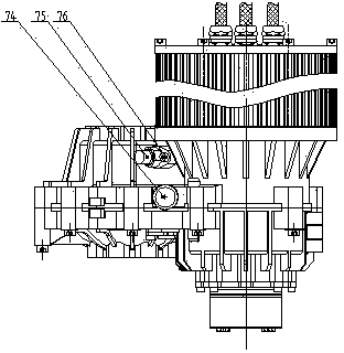
[0016]The technical scheme of the present invention is described in detail below in conjunction with accompanying drawing: be used in the electric vehicle power assembly on the electric vehicle, it mainly is made up of motor unit, transmission unit; Motor unit is made up of motor shaft 5, motor rotor 6, motor stator 7 , the motor housing 8, the motor end cover 3, the motor bearing 4, the motor stator lead wire 1, and the motor insulating bolt 2; The axial position of the rotor 6, after the motor bearing 4 and the motor shaft 5 are connected by interference fit, one end is matched with the bearing hole provided by the motor end cover 3, and the other end is connected with the bearing hole provided by the upper casing 68 of the transmission; the motor stator 7 It is connected with the motor housing 8 by interference fit, and the lead wire 1 of the motor stator 7 protrudes through the motor insulating bolt 2; The port is connected and fixed with bolts 9; the transmission unit is ...


PUM


Abstract

The invention relates to an electric vehicle motive power assembly, which consists of an electric motor unit and a speed changer unit, wherein the motive power of the electric motor unit is transmitted to a first-gear clutch input shaft and a second-gear clutch input shaft of a duplex clutch assembly through a motor shaft and an input shaft, is then transmitted to a first-gear driving gear or a second-gear driving gear through a clutch driving sheet and a clutch driven sheet of the duplex clutch assembly, is next transmitted to a middle shaft gear and a differential mechanism gear through a first-gear driven gear or a second-gear driven gear, and is finally output through a left half shaft gear and a right half shaft gear of an output shaft assembly, and an oil pump assembly lubricates the speed changer unit in a forced way and cools a motor assembly in a forced way. The electric vehicle motive power assembly has the advantages that the automatic gear shifting is realized through controlling the duplex clutch assembly, and the driving motor is enabled to always work in an ideal region, so the motive power performance and the economy of an electric automobile can be improved, the cost performance of the electric automobile is greatly improved, the design is ingenious, the structure is simple and compact, the use is convenient, and the electric vehicle motive power assembly is suitable for being popularized and applied in a large scale.

Description

technical field [0001] The invention relates to an electric vehicle power assembly and belongs to the technical field of electric vehicle drive systems. Background technique [0002] With the rise of fuel prices and the continuous enhancement of people's awareness of environmental protection, electric vehicles have the characteristics of "zero" emissions. At the same time, the working range of the motor is very wide. Its constant torque at low speed and constant power at high speed are very suitable for vehicle operation. Nowadays, most electric vehicles use fixed speed ratio reducers. Although the transmission method is simple, the manufacturing cost is low, and the maintenance cost is low; this is easy to generate noise, low efficiency, resonance, low energy utilization rate, and in most cases the efficiency is low. Very low areas, which waste precious battery energy and reduce driving range. According to the driving characteristics of electric vehicles, the driving motor...

Claims


Application Information

Patent Timeline
Patent Type & Authority Applications(China)
IPC IPC(8): B60K1/00B60K17/06F16H59/02
Inventor 胡如现胡悦胡阳
Owner 徐州铭尊机电有限公司
Learn More