
Internally coolable component for a gas turbine with at least one cooling duct

一种内部冷却、冷却通道的技术,应用在发动机元件、发动机功能、发动机的冷却等方向,能够解决叶片损坏等问题,达到降低压力损耗、低流动阻力、不降低冷却效果的效果

Inactive Publication Date: 2014-04-30
SIEMENS AG
View PDF4 Cites 2 Cited by
  • Summary
  • Abstract
  • Description
  • Claims
  • Application Information

AI Technical Summary

Problems solved by technology

This may result in damage to the blade

Method used


Image

  • Internally coolable component for a gas turbine with at least one cooling duct
  • Internally coolable component for a gas turbine with at least one cooling duct
  • Internally coolable component for a gas turbine with at least one cooling duct

Examples


Embodiment Construction

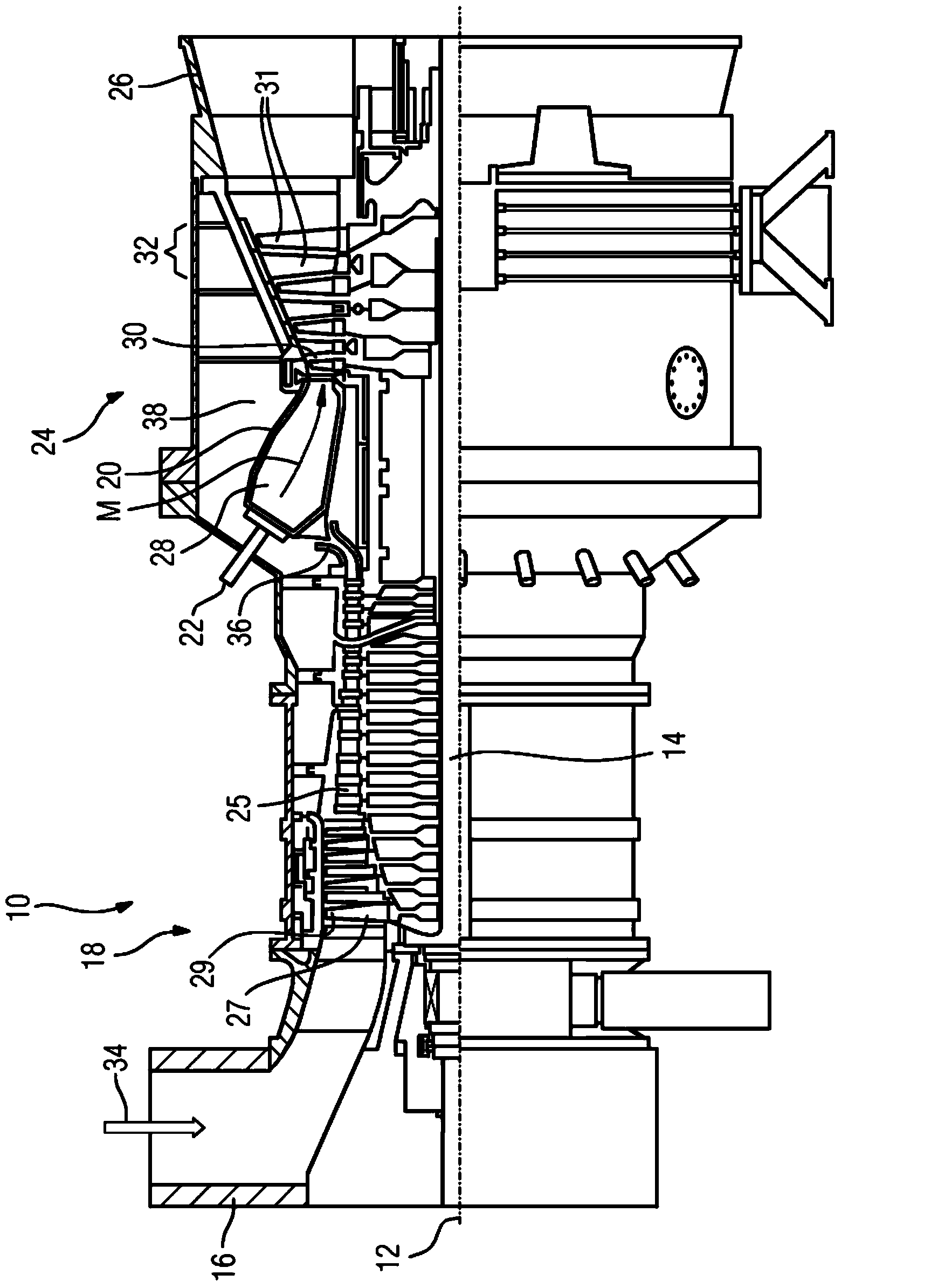
[0017] figure 1 The stationary gas turbine 10 is shown in longitudinal partial section. The gas turbine 10 has internally a rotor 14 mounted in rotation about an axis of rotation 12 , which is also referred to as a turbine rotor. Arranged in succession along the rotor 14 is a suction housing 16 , an axial turbocompressor 18 , a torus-shaped annular combustion chamber 20 with a plurality of burners 22 arranged rotationally symmetrically to one another, a turbine unit 24 and an exhaust housing. 26.

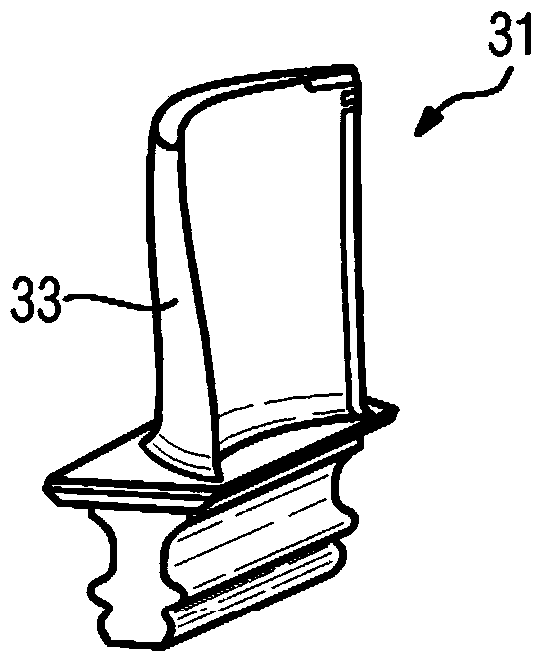
[0018] The axial turbocompressor 18 comprises an annular compressor channel 25 with successive compressor stages consisting of rotor blade rings and guide vane rings cascaded therein. The rotor blades 27 arranged on the rotor 14 lie opposite the outer channel wall with their freely ending airfoil tips 29 . The compressor channel 25 opens into a plenum 38 via a compressor output diffuser 36 . Arranged therein is an annular combustion chamber 20 with its combustion chamber 28 , wh...


PUM


Abstract

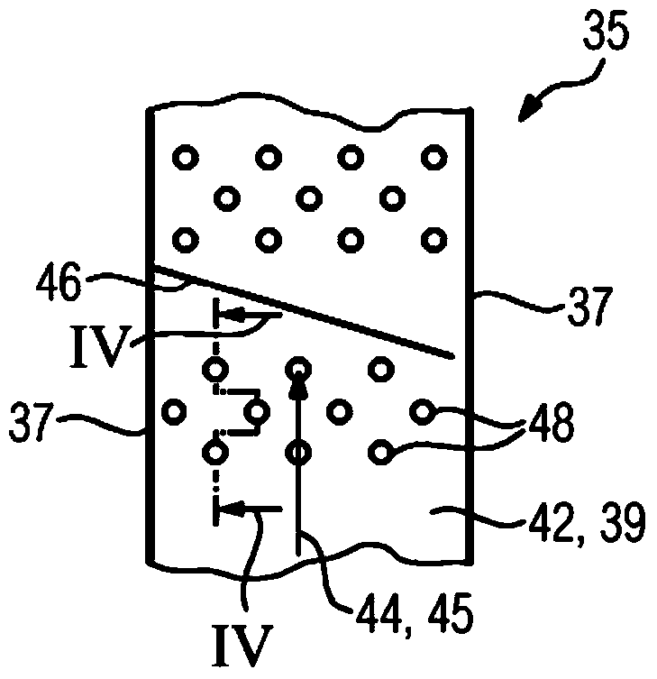
Overall, the invention relates to an internally coolable component for a gas turbine (10) with at least one cooling duct (35), on the inner surface (42) of which swirl elements (46) are arranged in the form of turbulators (46) which extend transversely with respect to the main flow direction of a coolant. In order to reduce pressure losses for the coolant (45) in the cooling duct (35), it is provided that pins (48) with different heights are set up between the turbulators (46).

Description

technical field [0001] The invention relates to an internally coolable component for a gas turbine, said component having at least one cooling channel, on the inner surface of which a swirl element in the form of a turbulator extending transversely to the main flow direction of a cooling medium is arranged. . Background technique [0002] As an internally coolable component of this type, for example, turbine blades of stationary gas turbines are known which have cooling channels arranged in a straight line or also in a meandering manner in the interior. A turbine blade of this type is known from EP1431514A2. Turbulators, also referred to as cooling fins, are usually arranged on their inner surfaces extending transversely to the main flow direction of the cooling medium, for example cooling air. The fins increase the heat transfer from the wall into the cooling medium, since the cooling medium is thus better mixed. At the same time, according to EP1431514A2, so-called pins...

Claims


Application Information

Patent Timeline
Patent Type & Authority Applications(China)
IPC IPC(8): F01D5/18
CPCF01D5/187F05D2260/22141F02C7/12
Inventor 马塞尔·埃菲尔丹尼尔·格洛斯安德烈亚斯·黑泽尔豪斯斯特凡·克隆普马尔科·林克乌维·西伯斯特凡·弗尔克迈克尔·瓦格纳
Owner SIEMENS AG
Learn More