
Power conversion device

A power conversion device and power conversion technology, which are applied to output power conversion devices, electrical components, and AC power input to AC power output, etc. The effect of commutation failure

Active Publication Date: 2014-04-23
NISSAN MOTOR CO LTD +1
View PDF7 Cites 0 Cited by
  • Summary
  • Abstract
  • Description
  • Claims
  • Application Information

AI Technical Summary

Problems solved by technology

[0003] However, in the existing control device of the power converter, only the voltage error caused by the commutation is compensated, and there is a problem that the failure of the commutation itself cannot be prevented

Method used


Image

  • Power conversion device
  • Power conversion device
  • Power conversion device

Examples


no. 1 Embodiment approach 》

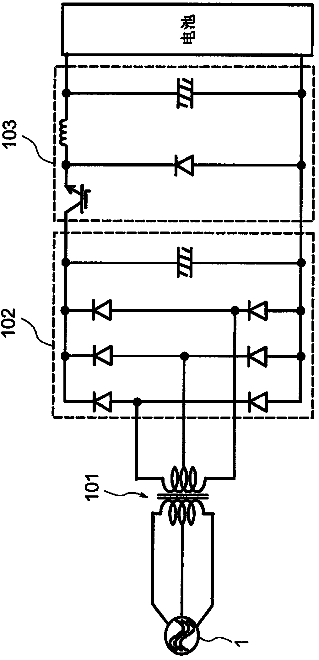
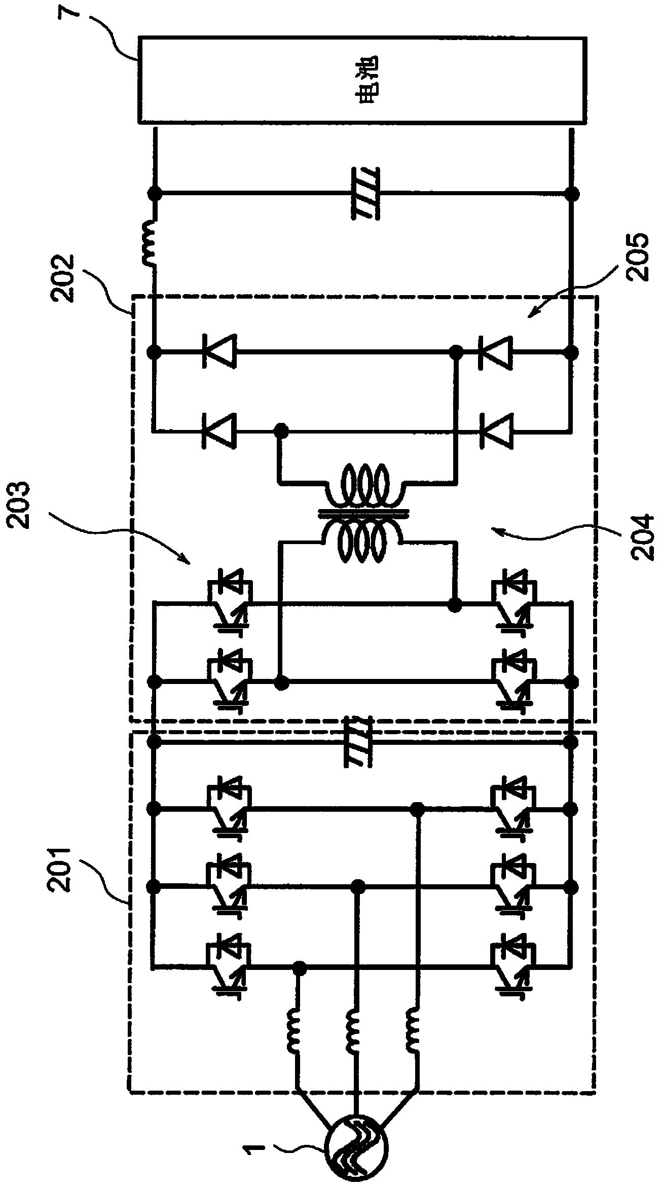
[0025] figure 1 It is a block diagram of a battery system including the power conversion device according to the embodiment of the present invention. Hereinafter, a case where the power conversion device of this example is applied to a charging device will be described as an example, but this example can also be applied to a control device that controls a motor or the like, or a vehicle including a motor.

[0026] The charging system of this example has an AC power source 1 , an input filter 2 , voltage sensors 31 to 33 , a matrix converter 4 , a high frequency transformer circuit 5 , an output filter 6 and a battery 7 .

[0027] The AC power source 1 is a three-phase AC power source and serves as a power source for the charging system. The input filter 2 is a filter for rectifying the AC power input from the AC power supply 1, and is constituted by an LC circuit of coils 21-23 and capacitors 24-26. The coils 21 to 23 are connected to the respective phases between the AC pow...


PUM


Abstract

A power conversion device comprises a conversion circuit having multiple-pair switching elements connected to each phase and converting an input AC power to an AC power. A first switching time is calculated that is the time required for: turning on the switching element of an upper arm circuit in one of the phases; turning off the switching elements of the upper arm circuit in the other phases; turning on at least one switching element of a lower arm circuit in the other phases; and turning off the switching element of the lower arm circuit in the one of the phases. A second switching time is also calculated that is the time required for turning on the switching element in the one of the phases and turning off the switching elements in the other phases. When making transition from the first switching time to the second switching time, among th e switching elements in the on-state, a switching element of either the upper arm circuit or the lower arm circuit is turned off and a switching element of the other arm circuit is maintained to be in the on-state.

Description

technical field [0001] The invention relates to a power conversion device. Background technique [0002] A control device for a power converter is known, the control device controls a power converter including a PWM rectifier for performing AC-DC conversion and an inverter connected to the PWM rectifier for performing DC-AC conversion. The structure of the inverter is characterized in that the control device has: a two-phase modulation unit, which generates an output voltage command for two-phase modulation of the inverter; Compensate the output voltage error generated during the two-phase modulation and correct the compensation amount for the output voltage command; the inverter PWM pattern generating unit generates the semiconductor switching element of the inverter based on the corrected output voltage command PWM pulse; rectifier PWM mode generation unit, which generates PWM pulses to the semiconductor switching elements of the PWM rectifier based on the input current c...

Claims


Application Information

Patent Timeline
Patent Type & Authority Applications(China)
IPC IPC(8): H02M5/293
CPCH02M5/293H02M7/217H02M5/458
Inventor 齐藤真生中村孝雅山本光治伊东淳一大沼喜也
Owner NISSAN MOTOR CO LTD
Learn More