Method for regulating accumulator pressure

A tube pressure, regulating loop technology, applied in the direction of fuel injection control, engine control, machine/engine, etc., can solve problems such as harsh regulation deviation

Active Publication Date: 2016-08-24
ROLLS ROYCE SOLUTIONS GMBH
View PDF7 Cites 0 Cited by
  • Summary
  • Abstract
  • Description
  • Claims
  • Application Information

AI Technical Summary

Problems solved by technology

Since there is no B-side I component in the regulator, this solution is critical in terms of remaining regulation deviation

Method used


Image

  • Method for regulating accumulator pressure
  • Method for regulating accumulator pressure
  • Method for regulating accumulator pressure

Examples


Embodiment Construction

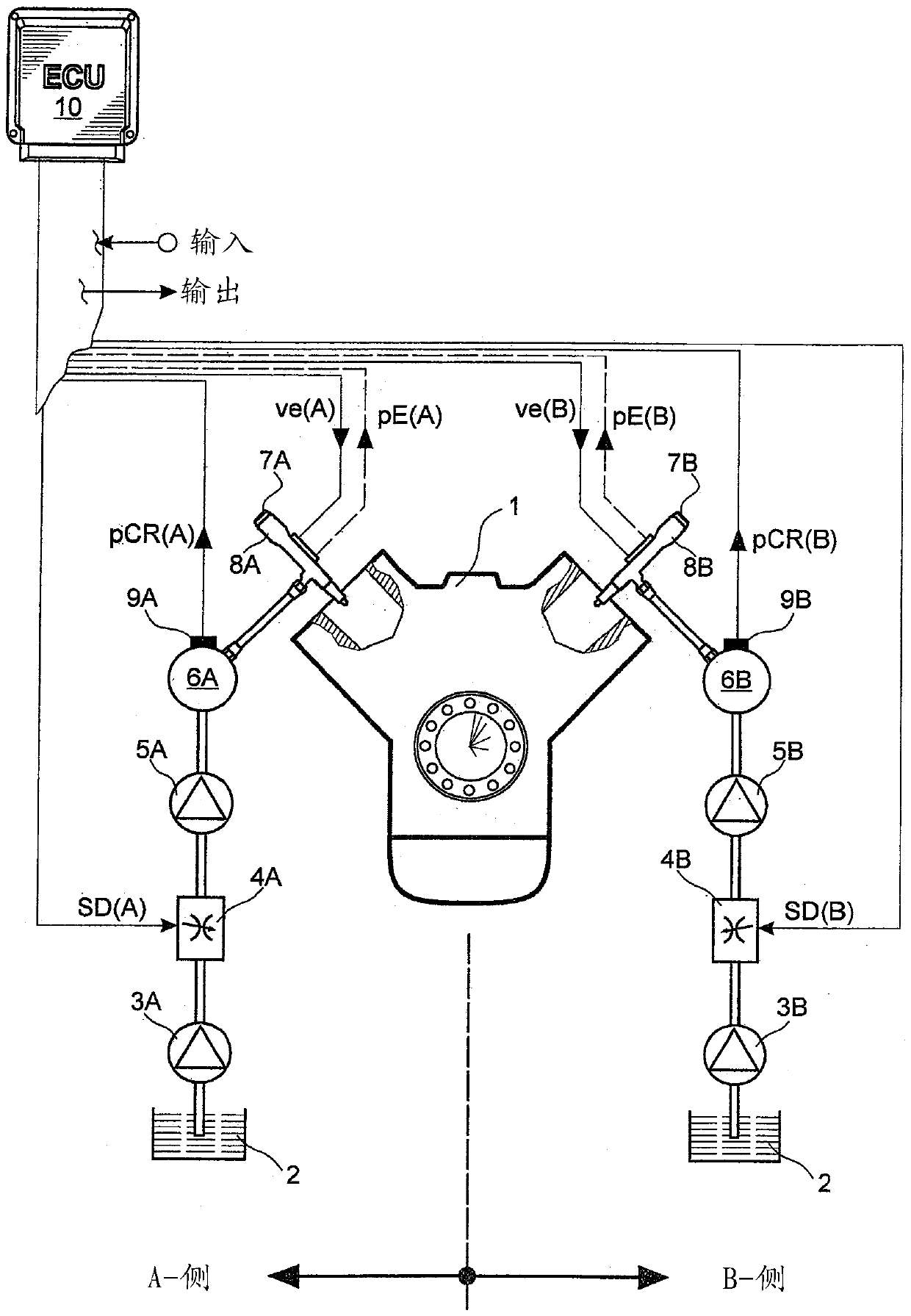
[0017] figure 1 A system diagram of an electronically controlled internal combustion engine 1 is shown with a common injection system on the A side and a common injection system on the B side. The common injection system on the A side comprises as mechanical part a low-pressure pump 3A for delivering fuel from the tank 2, a suction throttle 4A for influencing the volume flow, a high-pressure pump 5A, an accumulator 6A and a pump for injecting fuel. Injector 7A into the combustion chamber of internal combustion engine 1 . The common injection system on the B side consists of the same mechanical parts, which are identified by the same reference numerals appended with B.

[0018] Internal combustion engine 1 is controlled by electronic engine control unit 10 (ECU). exist figure 1 As input parameters of the electronic engine controller 10 are, for example, the A-side rail pressure pCR(A), the B-side rail pressure pCR(B) and the parameter EIN. The rail pressure pCR(A) on the A ...


PUM


Abstract

The invention proposes a method for regulating the accumulator pressure of a V-arranged internal combustion engine with different firing sequences, in which method the actual-accumulator pressure is calculated from the measured accumulator pressure, with the aid of the actual-accumulator The pressure and the theoretical rail pressure determine the control differential, and in this method a control variable for controlling the pressure regulator, in particular the suction restrictor, is calculated for regulating the rail pressure. The invention is characterized in that the actual - accumulator pressure is calculated from the measured accumulator pressure by means of an average value filter by obtaining the mean value of the accumulator pressure over a constant time below the limit speed (nLi) , and above the limiting speed (nLi) the mean value of the rail pressure over the working cycle of the internal combustion engine is obtained.

Description

technical field [0001] The invention relates to a method for regulating the accumulator pressure of a V-arranged internal combustion engine with different firing sequences. Background technique [0002] A V-arranged internal combustion engine has accumulators on the A side and the B side for the intermediate storage of fuel. Injectors are connected to the accumulator, through which fuel is injected into the combustion chamber. In the first embodiment of the rail-co-injection system, the individual high-pressure pumps deliver fuel under increased pressure in parallel into the two rails. The same rail pressure therefore exists in both rails. The second embodiment of the accumulator-common injection system differs in that the first high-pressure pump feeds into the first pressure accumulator and the second high-pressure pump feeds into the second pressure accumulator. Two structural forms are known, for example, from DE 43 35 171 . [0003] Since the combustion quality depe...

Claims


Application Information

Patent Timeline
Patent Type & Authority Patents(China)
IPC IPC(8): F02D41/38
CPCF02D41/3845F02D2041/1432F02D2041/286F02D2041/3881F02D2200/0602F02D41/14
Inventor A.德尔克
Owner ROLLS ROYCE SOLUTIONS GMBH
Why Eureka
Try Eureka