
Optically stimulated luminescence dosage tester

A dosimetry and optical luminescence technology, applied in fluorescence/phosphorescence, material excitation analysis, etc., can solve the problems of not focusing on the influence of adjacent samples, the gap of the optical fiber can not pass the light, and the effective light transmission area is reduced, so as to simplify the sample lifting equipment, increased optical coupling efficiency, and ease of attachment and detachment

Inactive Publication Date: 2014-04-23
河北地质大学
View PDF5 Cites 2 Cited by
  • Summary
  • Abstract
  • Description
  • Claims
  • Application Information

AI Technical Summary

Problems solved by technology

[0004] Some papers and patent documents that have been published so far have mentioned the use of optical fibers for the transmission of excitation light, but the interface loss is very large, and the influence of adjacent samples has not been considered.
The optical fiber in the prior art is an optical fiber bundle composed of multiple optical fibers. Not only the gaps between multiple optical fibers cannot pass light, but also the existence of the optical fiber coating layer reduces the effective light transmission area.
The usual optical luminescence test uses a sample lifting mechanism to lift the sample upwards, and the excitation light source directly illuminates the surface of the sample. This excitation method not only reduces the emission efficiency of the light source, but also affects the measurement of adjacent samples.

Method used


Image

  • Optically stimulated luminescence dosage tester
  • Optically stimulated luminescence dosage tester
  • Optically stimulated luminescence dosage tester

Examples


Embodiment 1

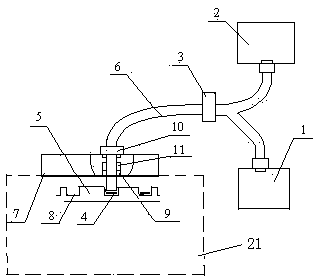
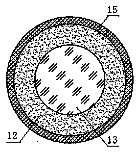
[0028] Optical Luminescent Dosimeter of the present invention such as figure 1 As shown, it includes an excitation light source 1, a photomultiplier tube 2, a beam splitter 3, a plastic optical fiber 6, a measuring instrument cover 7, a sample tray 5, a measuring instrument body 21, and an optical fiber moving mechanism. The optical fiber moving mechanism is fixed on the measuring instrument upper cover. superior. The optical fiber moving mechanism is connected with one end of the plastic optical fiber, and the other end of the plastic optical fiber is divided into two paths through a beam splitter, one path is connected to the excitation light source, and the other path is connected to the photomultiplier tube. Such as image 3 As shown, the plastic optical fiber 6 is composed of a single optical fiber core 13, an optical fiber coating layer 12 and an optical fiber outer layer 15, and the diameter of the optical fiber core is 10 mm. Depend on Figure 12 It can be seen that...

Embodiment 2

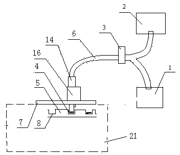
[0032] Another embodiment of the present invention, as shown in 2, includes an excitation light source 1, a photomultiplier tube 2, a beam splitter 3, a plastic optical fiber 6 and a measuring instrument body 21, and the measuring instrument body is provided with a measuring instrument upper cover 7 and a sample tray 5 And the worm gear moving mechanism, the worm gear moving mechanism includes a transmission device 14 and a motor module 16. One end of the plastic optical fiber is connected to the worm gear moving mechanism, and the other end is divided into two paths by a beam splitter, one path is connected to the excitation light source, and the other path is connected to the photomultiplier tube.

[0033] Such as Figure 5-7As shown, the transmission device is composed of a worm wheel 22, a worm screw 23 and a rack frame 25, and the motor module is provided with a stepping motor 24. The motor module is fixed on the measuring instrument upper cover 7, and the rack frame 25 ...

Embodiment 3

[0037] Yet another embodiment of the present invention is as Figure 8 As shown, the analyzer is provided with a sleeve 27 and a focusing lens 26 . The optical fiber moving mechanism is a magnetic flux moving mechanism, including a magnetic flux material 9, an optical fiber chuck 10, a positioning block 11 and a spring 17. The magnetic flux material, the optical fiber chuck, and the positioning block are provided with openings having the same outer diameter as the plastic optical fiber. The optical fiber chuck is fixed on the top of the measuring instrument upper cover 7 by bolts 19, and the magnetic flux material is fixed on the lower part of the measuring instrument upper cover by bolts. The plastic optical fiber 6 passes through the fiber clamp and is bonded on the positioning block with glue 18, one end of the spring is fixed on the positioning block, and the other end is fixed on the optical fiber clamp. The sleeve 27 is connected to the opening of the magnetic flux mate...


PUM

PropertyMeasurementUnit
Diameteraaaaaaaaaa
Diameteraaaaaaaaaa

Abstract

The invention relates to an optically stimulated luminescence dosage tester. The optically stimulated luminescence dosage tester comprises an excitation light source, a photomultiplier, a beam splitter, a tester upper cover, a sample tray, a tester machine body, a plastic optical fiber and an optical fiber travel mechanism, wherein the optical fiber travel mechanism is fixed on the tester upper cover, a magnetic flow travel mechanism or a worm and gear travel mechanism is adopted as the optical fiber travel mechanism, the plastic optical fiber comprises a single optical fiber core, an optical fiber coating layer and an optical fiber outer layer, wherein the diameter of the optical fiber core is 8-15mm; the optical fiber travel mechanism is connected with one end of the plastic optical fiber, the other end of the plastic optical fiber is divided into two paths by the beam splitter, and the two paths are respectively connected to the excitation light source and the photomultiplier; a detachable drivepipe and a focusing lens are arranged at the front end of the optical fiber travel mechanism of the optically stimulated luminescence dosage tester. The optically stimulated luminescence dosage tester uses large diameter plastic optical fiber, so that the optical coupling efficiency is improved, and the light source excitation strength is improved; the optical fiber travel mechanism can accurately control the position of the optical fiber, reduces the influence of the excitation light source on adjacent samples, and can be used for measuring common samples and single grain samples.

Description

technical field [0001] The invention belongs to the technical field of geological age measuring equipment, and relates to an optical luminescence dose meter, in particular to an optical luminescence dose meter with an optical fiber moving mechanism. Background technique [0002] The defects produced during the formation of solid mineral crystals and the radiation brought to it by the acquired environment will cause lattice defects inside the crystal, forming free energy storage electrons, and the energy storage electrons stored in the crystal are stimulated by external energy. Photons are emitted. The method of using light energy to excite mineral crystals is called optical luminescence. OSL is a kind of phosphorescence. For the same mineral crystal, under a fixed light source and the same excitation conditions, the total amount of OSL photons is proportional to the total amount of energy-storing electrons in the solid, that is, the radiation received by the crystal The do...

Claims


Application Information

Patent Timeline
IPC IPC(8): G01N21/64
Inventor 梁萍亢俊健刘强文继华
Owner 河北地质大学
Learn More