
Automatic feeding mechanism

A technology of automatic feeding and receiving plates, which is applied to conveyor objects, transportation and packaging, etc., can solve problems such as affecting the normal operation of equipment and products that cannot be transported, and achieve the effect of improving safety, reliability and stability.

Inactive Publication Date: 2014-04-23
KUNSHAN FOR EASIER AUTOMATION TECH
View PDF0 Cites 3 Cited by
  • Summary
  • Abstract
  • Description
  • Claims
  • Application Information

AI Technical Summary

Problems solved by technology

[0003] In order to solve the problem that in the prior art, the belt transports the product to the receiving plate that is docked at the back, when the product touches the receiving plate, due to the certain friction between the product and the receiving plate, the product cannot be transported to the feeding channel of the receiving plate. The problem that affects the normal operation of the equipment, the present invention provides an automatic feeding mechanism that is simple in structure, easy to use, maintains the normal conveying force of the belt, and can normally convey products

Method used

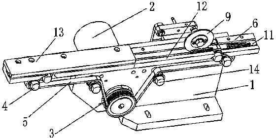
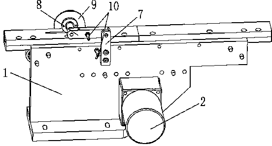

Image

  • Automatic feeding mechanism
  • Automatic feeding mechanism

Examples


Embodiment Construction

[0013] Below in conjunction with accompanying drawing, the present invention will be further described:

[0014] Such as Figure 1-2 As shown, an automatic feeding mechanism includes a base 1, a motor 2, a synchronous pulley 3, a transition wheel 4, a belt 5, a receiving plate 6, a vertical connecting plate 7, a horizontal connecting plate 8, a friction wheel 9, an adjusting screw, Bolts and torsion springs 10 are provided with a motor 2 at the back of the base 1, and the motor 2 passes through the base 1 and is connected with the synchronous pulley 3 positioned at the front of the base 1, and transition wheels 4 are respectively arranged at both ends of the front of the base 1, so The synchronous pulley 3 is connected with the two transition wheels 4 through a belt 5, and the end of the belt 5 in the running direction is docked with the feedway 11 provided with the feed plate 6 on the top of the base 1, and a vertical connecting plate 7 is fixed on the back of the base 1. Th...


PUM


Abstract

The invention discloses an automatic feeding mechanism. The automatic feeding mechanism comprises a base, a motor, a synchronous pulley, transition wheels, a belt and a material collecting plate and is characterized by also comprising a vertical connecting plate, a horizontal connecting plate, a friction wheel and an adjusting screw; the motor which is arranged on the rear side of the base penetrates the base to be connected with the synchronous pulley which is arranged on the front side of the base; the transition wheels are arranged at two ends on the front side of the base; the synchronous pulley is connected with the transition wheels which are arranged at the two ends through the belt; the tail end of the belt moving direction is in butt joint with the material collecting plate which is arranged at the top of the base; the vertical connecting plate is fixed on the rear side of the base; the horizontal connecting plate is fixed at the top of the vertical connecting plate; a free end of the horizontal connecting plate is connected with the friction wheel through a rotary shaft; the friction wheel is in contact with the belt which is arranged under the friction wheel; the adjusting screw penetrates the horizontal connecting plate to be connected with a screw hole which is formed in the top of the base. The automatic feeding mechanism has the advantages of being simple in structure and convenient to use, maintaining the normal conveying force of the belt and enabling products to be normally conveyed.

Description

technical field [0001] The invention relates to a feeding mechanism, in particular to an automatic feeding mechanism. Background technique [0002] At present, the belt is used to convey the product to the receiving plate that is docked at the back. When the product touches the receiving plate, due to the certain friction between the product and the receiving plate, the product cannot be transported to the material channel of the receiving plate. It will cause a lot of trouble, which will affect the normal operation of the equipment and delay the subsequent processing and production. Contents of the invention [0003] In order to solve the problem that in the prior art, the belt transports the product to the receiving plate that is docked at the back, when the product touches the receiving plate, due to the certain friction between the product and the receiving plate, the product cannot be transported to the feeding channel of the receiving plate. The problem that affects...

Claims


Application Information

Patent Timeline
Patent Type & Authority Applications(China)
IPC IPC(8): B65G47/04
Inventor 郭池洪操林曹洪胜
Owner KUNSHAN FOR EASIER AUTOMATION TECH
Learn More