
Water turbine transmission mechanism with controllable output

A technology of transmission mechanism and hydraulic turbine, which is applied in the direction of machines/engines, engine components, hydroelectric power generation, etc., can solve the problem of high mortality rate, achieve the effect of reducing the overall volume, ensuring output and operating efficiency, and simplifying the overall structure

Pending Publication Date: 2018-11-30
STATE GRID CORP OF CHINA +2
View PDF1 Cites 3 Cited by
  • Summary
  • Abstract
  • Description
  • Claims
  • Application Information

AI Technical Summary

Problems solved by technology

[0004] In view of the high mortality of fish passing through the dam and the high mortality of fish passing through the water turbine in the field of hydropower generation, a controllable output type water turbine transmission mechanism is provided to reduce the death rate of fish passing through the water turbine and ensure the output of the water turbine. and operating efficiency

Method used


Image

  • Water turbine transmission mechanism with controllable output
  • Water turbine transmission mechanism with controllable output
  • Water turbine transmission mechanism with controllable output

Examples


Embodiment 1

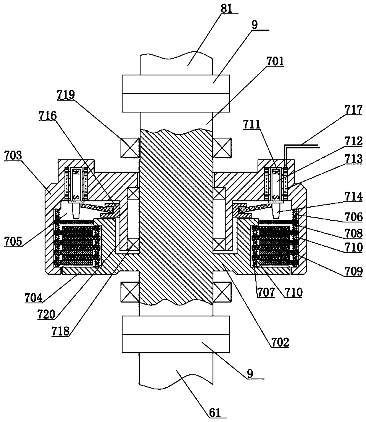
[0017] Embodiment 1: The upstream of the water area communicates with the power generation area of ​​the downstream water turbine 5 through the water diversion channel 4, and the water potential enters the interior of the water turbine 5 to drive the runner blades 6 to rotate, and then drive the generator 8 to generate electricity. Such as figure 1 As shown, the position of the water outlet in the upstream water area is sequentially provided with fish gate 2 and water gate 3 from front to back, and the opening and closing are controlled by the lifting motor respectively. Therefore, when the fish gate 2 is closed and the water gate 3 is opened, the water turbine 5 can generate electricity freely, or generate electricity under control. When opening fish gate 2 and opening water gate 3, it is the period of passing fish. At this time, tools such as fish luring light 1 were also set at the outlet position of upstream waters, and such devices as figure 2 The transmission mechanism...

Embodiment 2

[0026] Embodiment 2: On the basis of Embodiment 1, the pushing mechanism is different. Specifically, on the inner wall of the outer shell 703 in the annular cavity 705, there are a plurality of fixed shafts parallel to the axial direction evenly distributed along the same ring. The slots are equipped with hydraulic push rods, gas push rods or electric push rods in each fixed slot.


PUM


Abstract

The invention discloses a water turbine transmission mechanism with controllable output. An annular inner shell is fixedly connected to a mandrel through a connecting ring, meanwhile, the inner shellis sleeved with an outer shell, an annular inner cavity is defined by the outer shell and the inner shell, outer ring axial sliding rods are evenly distributed on the inner wall of the outer shell, inner ring axial sliding rods are evenly distributed on the outer wall of the inner shell, the outer ring axial sliding rods are sleeved with multiple outer ring friction pieces, the inner ring axial sliding rods are sleeved with multiple inner ring friction pieces, and multiple pushing and driving mechanisms parallel to the axial direction are evenly distributed on the inner wall of the outer shell. The rotating speed of a runner can be changed and the runner can stop rotating by controlling the pushing and driving mechanisms, the interference degree of runner blades on an inner bin of a waterturbine is controlled, and therefore a safety passageway can be provided for upstream and downstream fishes. By means of the water turbine transmission mechanism, an upstream fish gate can be controlled to be opened and reduced or the water turbine can stop working in the fish flow period, and a condition is provided for timing automatic control.

Description

technical field [0001] The invention belongs to the hydraulic turbine transmission technology in the field of hydraulic ecological engineering, and in particular relates to a hydraulic turbine transmission mechanism with controllable output. Background technique [0002] Hydropower generation uses the water potential to drive the rotor blades of the water turbine to rotate, which in turn drives the generator to rotate to generate electricity. During the working process of the water turbine, the rotating blades will cause harm to the fish. During the long-term work, the fish will continue to be harmed. The existing hydroelectric power generation device usually cuts off the upstream and downstream channels of the fish, and relies on upward migration to complete the process. Migratory fish have a strong impact on the life cycle, and there are also impacts on non-migratory fish. Fish will suffer serious injuries as they descend through ordinary water turbines. Studies by some ...

Claims


Application Information

Patent Timeline
Patent Type & Authority Applications(China)
IPC IPC(8): F03B11/00F03B15/00F03B13/00
CPCF03B11/00F03B13/00F03B15/00Y02E10/20
Inventor 靳国云王从显李长胜罗胤徐学兵董政淼王坤曹永闯赵俊杰杨恒乐秦连乐
Owner STATE GRID CORP OF CHINA
Learn More