An H-shaped steel eccentric positioning clamping device

A technology for positioning and clamping, H-beam, applied in auxiliary devices, auxiliary welding equipment, welding/cutting auxiliary equipment, etc. Work intensity, the effect of improving process quality and production efficiency

Inactive Publication Date: 2015-09-30
HUBEI HONGYI STEEL CONSTR ENG
View PDF8 Cites 0 Cited by
  • Summary
  • Abstract
  • Description
  • Claims
  • Application Information

AI Technical Summary

Problems solved by technology

[0002] H-shaped steel is widely used in steel structure engineering as the main load-bearing member of steel structure buildings. H-shaped steel needs to be positioned and clamped during the welding process. However, the existing technology uses a symmetrical clamping mechanism to position the H-shaped steel. The symmetric The clamping mechanism is set in the movable clamping roller B in the cage and is equipped with a central rotating shaft A, and the two driving rollers C that drive the clamping roller in situ are arranged symmetrically on both sides of the center line of the clamping roller B, such as Figure 7 As shown, when positioning the variable cross-section H-shaped steel, because the central rotating shaft A is easy to rotate, when the head end of the variable-section H-shaped steel just enters the pinch roller B, it cannot be reliably positioned, and the workpiece must be transported forward for a certain distance before forming reliable positioning. Welding can only be carried out after the workpiece is reliably positioned; when welding reaches the end of the workpiece, the center rotation axis A starts to rotate because the clamping positioning roller B is separated from the workpiece one after another. At this time, the positioning fails and the welding is terminated. When the welding positioning is performed by the tightening mechanism, there is a section of weld seam at the head and end of the variable-section H-shaped steel that cannot be welded. To complete the full welding of the H-shaped steel, arc strikers must be added at the head and end. low, which seriously hinders the development of steel structures. Therefore, it is inevitable to develop a positioning clamping device with a more reasonable structure.

Method used


Image

  • An H-shaped steel eccentric positioning clamping device
  • An H-shaped steel eccentric positioning clamping device
  • An H-shaped steel eccentric positioning clamping device

Examples


Embodiment 1

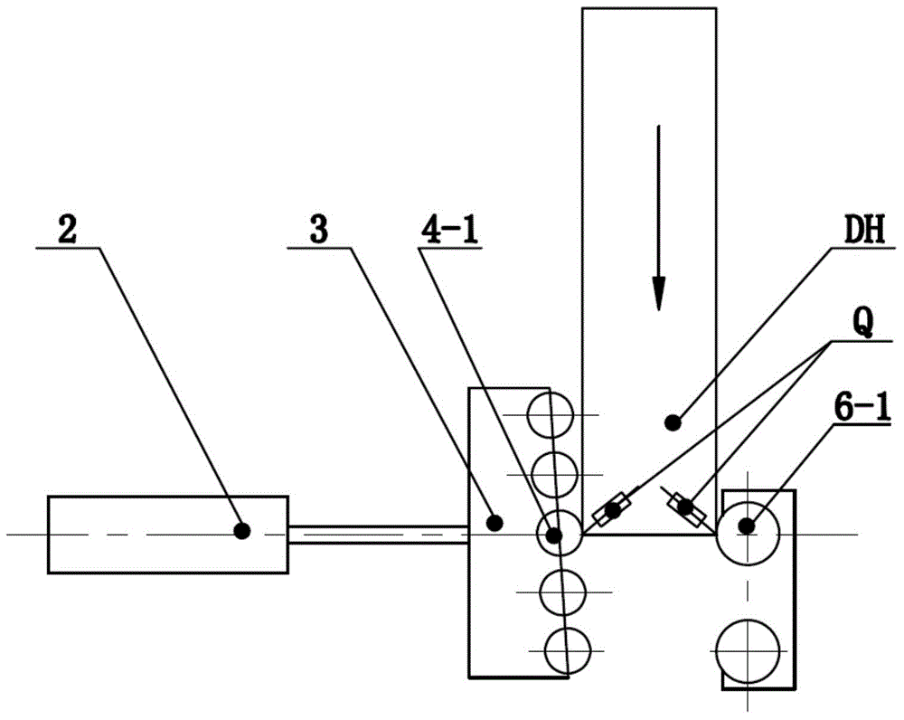
[0021] Embodiment 1. When the positioning and clamping device of the present invention is used for positioning and clamping of H-shaped steel with equal cross-section, since the present invention does not set a central rotating shaft, there is no problem of positioning failure caused by the overall rotation deviation of the clamping roller 4, DH The head end is delivered to such as image 3 In the position shown, the central roller shaft 4-1 of the eccentric clamping roller 4 and the driving wheel 6-1 arranged on the same centerline form two reliable positioning points, so the welding torch Q arranged above the corresponding welding seam is aligned with H Precise welding is carried out on the weld seams on both sides of the profile steel; when the workpiece is welded to the end such as Figure 4 In the position shown, although the central roller shaft 4-1 is separated from the tail end of the workpiece, there is still a reliable clamping of the clamping roller shaft and the wo...

Embodiment 2

[0022] Embodiment 2, when the positioning and clamping device of the present invention is used for the positioning and clamping of variable-section H-shaped steel, it effectively solves the reliable clamping and positioning of the head and end of the H-shaped steel, and the variable-section H-shaped steel BH head is transported to such as Figure 5 In the position shown, the central roller shaft 4-1 of the eccentric clamping roller 4 and the driving wheel 6-1 arranged on the same centerline form two reliable positioning points, so the welding torch Q arranged above the corresponding welding seam is aligned with H Precise welding is carried out on the weld seams on both sides of the profile steel; when the workpiece is welded to the end such as Figure 6 In the position shown, the central roller shaft 4-1 and the driving wheel 6-1 can still form two reliable positioning points, and after the welding torch Q closes the arc, the full welding process of the variable cross-section H...


PUM


Abstract

The invention provides an H-shaped steel eccentric location clamping device and belongs to the field of machining devices. H-shaped steel driving clamping rolls and H-shaped steel movable clamping rolls are arranged on two sides of an H-shaped steel frame respectively. The movable clamping rolls are evenly and vertically arranged in a holder at intervals with eccentric angles in the direction opposite to the H-shaped steel conveying direction, and the two driving clamping rolls are arranged at intervals in the H-shaped steel conveying direction in the front-back mode. A radial center line of a center roll of the movable eccentric clamping rolls and a rear roll of the driving clamping rolls and an axial center line of a cylinder pushing shaft of the movable clamping rolls are located on the same horizontal straight line. A center rotating shaft is cancelled, an electric location clamping mechanism with the eccentric angle being 8-30 degrees is innovatively adopted, and the problem that the existing symmetrical clamping mechanism is easy to rotate during clamping location and causes location failure is solved thoroughly. The eccentric location clamping device is widely applied to H-shaped steel with identical sections and variable sections, effectively achieves reliable clamping location of the head end and the tail end of the H-shaped steel and improves machining quality and production efficiency of the H-shaped steel.

Description

technical field [0001] The invention relates to an eccentric positioning and clamping device for H-shaped steel, which belongs to the field of mechanical processing equipment. Background technique [0002] H-shaped steel is widely used in steel structure engineering as the main load-bearing member of steel structure buildings. H-shaped steel needs to be positioned and clamped during the welding process. However, the existing technology uses a symmetrical clamping mechanism to position the H-shaped steel. The symmetric The clamping mechanism is set in the movable clamping roller B in the cage and is equipped with a central rotating shaft A, and the two driving rollers C that drive the clamping roller in situ are arranged symmetrically on both sides of the center line of the clamping roller B, such as Figure 7 As shown, when positioning the variable cross-section H-shaped steel, because the central rotating shaft A is easy to rotate, when the head end of the variable-section H...

Claims


Application Information

Patent Timeline
Patent Type & Authority Patents(China)
IPC IPC(8): B23K37/04
CPCB23K37/0435
Inventor 吴顺红罗泽平黄胜王军张军
Owner HUBEI HONGYI STEEL CONSTR ENG
Why Eureka
Try Eureka