
Shell for projector

A technology for projectors and casings, which is applied in the fields of electrical equipment casings/cabinets/drawers, instruments, optics, etc. It can solve the problems of lens damage, waste of users, and non-use of skateboard positioning, etc., and achieves the effect of convenient operation and simple structure

Inactive Publication Date: 2014-04-16
KUNSHAN HUAKUI MACHINERY ELECTRONICS
View PDF4 Cites 0 Cited by
  • Summary
  • Abstract
  • Description
  • Claims
  • Application Information

AI Technical Summary

Problems solved by technology

And in order to use the projector at the fastest speed, some users take off the projector cover and throw the projector cover aside, so they often find that the projector cover is lost after they use the projector, and the user needs to buy it again projector cover
This will waste the user's time and money to buy a new projector cover, and when the user loses the projector cover, it is generally impossible to immediately buy a new projector cover to protect the lens, which may cause the lens to lose its short-term The lens without protection is likely to be damaged, and the lens is an important part of the projector. If the lens is damaged without the protection of the lens cover, it may lead to the scrapping of the projector, and some projectors The accessory lacks a limit device, which does not use the positioning of the skateboard and cannot meet people's needs

Method used


Image

  • Shell for projector
  • Shell for projector
  • Shell for projector

Examples


Embodiment Construction

[0015] In order to make the object, technical solution and advantages of the present invention clearer, the present invention will be further described in detail below in conjunction with the accompanying drawings and embodiments. It should be understood that the specific embodiments described here are only used to explain the present invention, not to limit the present invention.

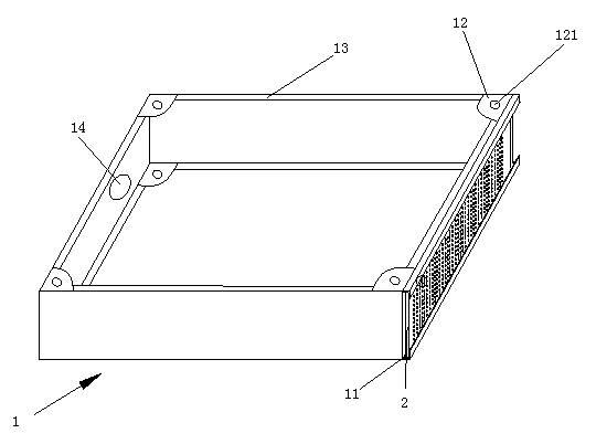
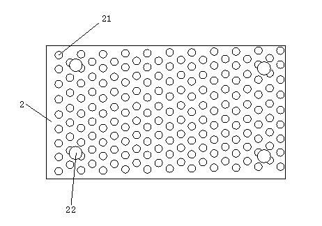
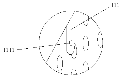
[0016] see figure 1 , figure 2 with image 3 , figure 1 It is a structural schematic diagram of the present invention, figure 2 for figure 1 Schematic diagram of the structure of the cooling plate, image 3 for figure 1 Partial enlarged view of the middle fixing seat.

[0017] Described a kind of shell that is used on the projector comprises frame body 1 and heat dissipation plate 2, and the right end of described frame body 1 is provided with chute 11, and described chute 11 is provided with fixing seat 111, and described fixing seat There are two 111, and evenly distributed on the chute...


PUM


Abstract

The invention relates to a shell for a projector. The shell for the projector comprises a frame body and a heat dissipation plate, wherein a sliding chute is formed in the right end of the frame body, fixing bases are arranged on the sliding chute, arc-shaped installing plates are further arranged on the frame body, oval holes are further formed in the arc-shaped installing plates, blocking edges are further arranged on the frame body, heat dissipation holes and installing holes are formed in the heat dissipation plate, and each installing hole is formed between two corresponding adjacent heat dissipation holes. According to the shell for the projector, due to the fact that each installing hole is formed between two corresponding adjacent heat dissipation holes, the heat dissipation plate can be easily fixed to the sliding chute, and the functions that the heat dissipation effect is not influenced, and the fixation effect is achieved are further achieved; due to the fact that the blocking edges and an arc-shaped installing base are arranged, a shielding plate can be fixed, installation of other components of the projector can be facilitated, and the shell is simple in structure, convenient to operate, economical and practical.

Description

technical field [0001] The invention relates to an auxiliary accessory of a projector, in particular to a casing used on a projector. Background technique [0002] Most of the projector lens caps on the market are separated from the projector lens. Whenever the user wants to use the projector, he needs to remove the projector cap and keep the lens cap properly before turning on the projector. The projector can only be used. And in order to use the projector at the fastest speed, some users take off the projector cover and throw the projector cover aside, so they often find that the projector cover is lost after they use the projector, and the user needs to buy it again Projector cover. This will waste the user's time and money to buy a new projector cover, and when the user loses the projector cover, it is generally impossible to buy a new projector cover immediately to protect the lens, which may cause the lens to lose its short-term The lens without protection is likely...

Claims


Application Information

Patent Timeline
Patent Type & Authority Applications(China)
IPC IPC(8): G03B21/14G03B21/16H05K5/00
Inventor 严凤良
Owner KUNSHAN HUAKUI MACHINERY ELECTRONICS
Learn More