A sock steam setting machine
A steam setting and setting machine technology, applied in the direction of setting/stretching loop fabrics, heating/cooling fabrics, textiles and papermaking, etc., can solve the problems of insufficient setting, unqualified socks, high cost, etc., to save water resources and Production cost, high degree of automation, and the effect of improving efficiency
- Summary
- Abstract
- Description
- Claims
- Application Information
AI Technical Summary
Problems solved by technology
Method used
Image
Examples
Embodiment 1
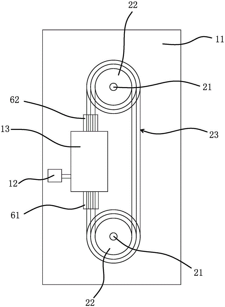
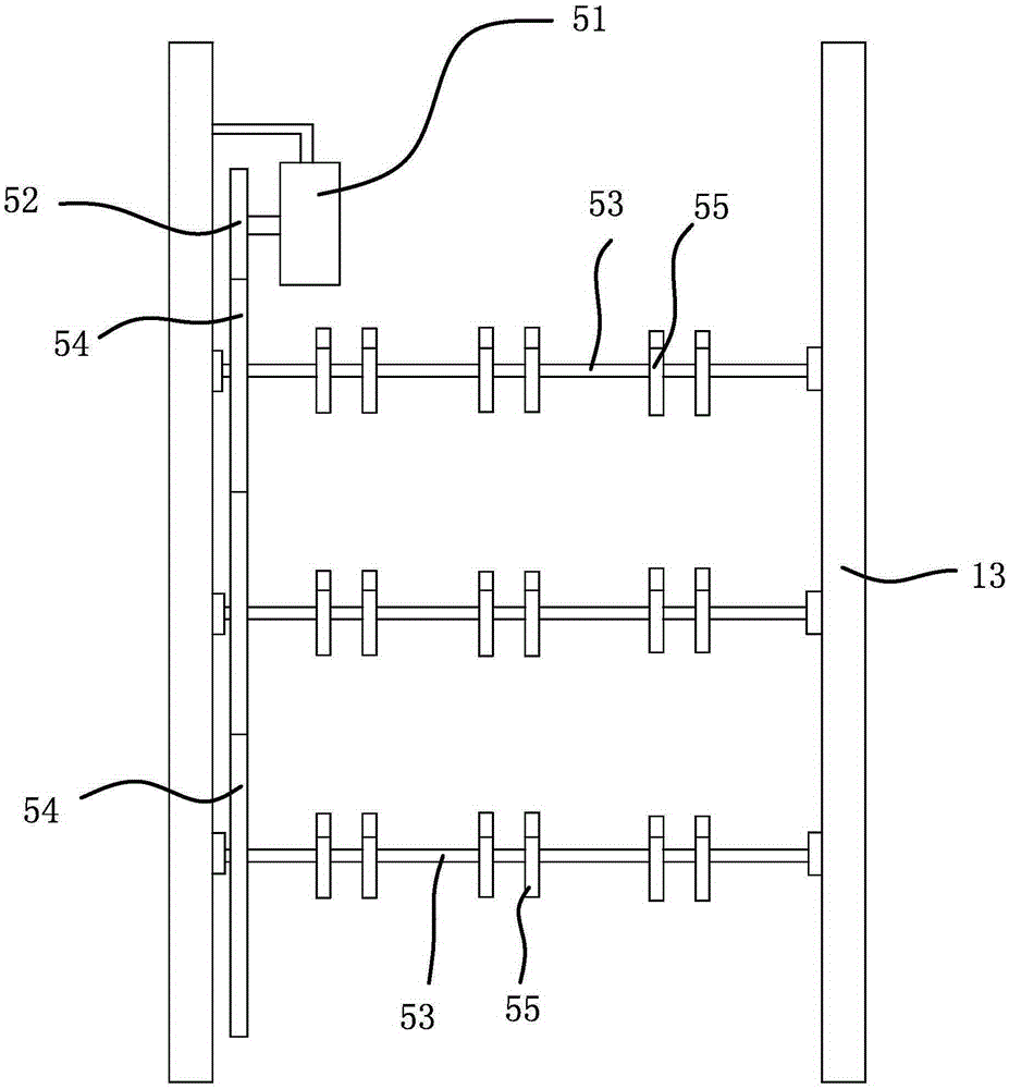
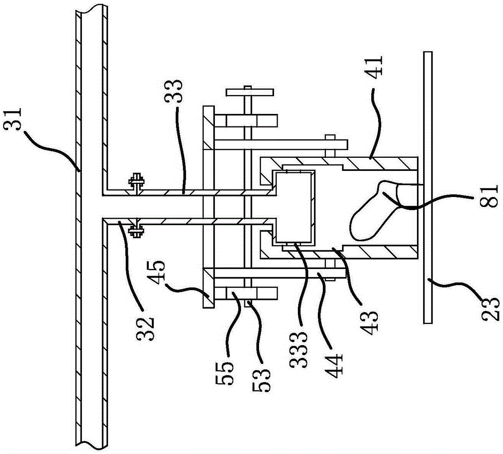
[0026] A sock steam setting machine, such as figure 1 Shown, comprise frame 11, steam generator 12, steam setting room 13 and controller, the steam generator 12 used among the present invention is prior art, is that can buy on the market, and controller is single-chip microcomputer; Frame 11 is rotatably connected with two drive shafts 21, which are driven by a drive motor, and a number of transmission sprockets 22 are sequentially fixed on the drive shaft 21 along its axis, and the diameters of the transmission sprockets 22 decrease successively from top to bottom, and the drive shaft 21 is connected with transmission chain 23 between the transmission sprockets 22 of equal diameter, and one side of transmission chain 23 all passes through steam setting chamber 13, and socks cover plate 81 is all fixed on every transmission chain 23, and socks cover plate 81 The number of sock covers 81 is evenly distributed along the length direction of the transmission chain 23 and each tran...
Embodiment 2
[0036] The structure and principle of this embodiment are basically the same as that of Embodiment 1. The difference is that the control mechanism includes control cylinder 1, control cylinder 2 and a control rod. Two connecting rods are fixed on the pipe wall of the gas collecting pipe. On both sides of the gas collecting pipe, the upper end of the connecting rod is fixed with a lifting ring. The control cylinder 1 and the control cylinder 2 are fixed on the top of the steam calibrating chamber. The control cylinder 1 and the control cylinder 2 are respectively located at the exit and entrance of the steam calibrating chamber. Main rod 1 fixed by the piston rod of cylinder 1, main rod 2 fixed to the piston rod controlling cylinder 2, and several sub-rods between main rod 1 and main rod 2 corresponding to steam pipelines one by one, sub-rods and steam pipelines Parallel, the sub-rod passes through the suspension ring, and the first control cylinder and the second control cylind...
PUM
 Abstract
Description
Claims
Application Information
 - R&D
- Intellectual Property
- Life Sciences
- Materials
- Tech Scout
- Unparalleled Data Quality
- Higher Quality Content
- 60% Fewer Hallucinations
Browse by: Latest US Patents, China's latest patents, Technical Efficacy Thesaurus, Application Domain, Technology Topic, Popular Technical Reports.
© 2025 PatSnap. All rights reserved.Legal|Privacy policy|Modern Slavery Act Transparency Statement|Sitemap|About US| Contact US: help@patsnap.com


