Eureka AIR delivers breakthrough ideas for toughest innovation challenges, trusted by R&D personnel around the world.

Device for grinding pipeline socket

A grinding and pipeline technology, which is applied to grinding drive devices, machine tools suitable for grinding workpiece planes, and parts of grinding machine tools. It can solve the problems of large energy consumption and uneven cleaning, so as to ensure the grinding effect Effect

Active Publication Date: 2014-04-16
XINXING DUCTILE IRON PIPES CO LTD
View PDF5 Cites 7 Cited by
  • Summary
  • Abstract
  • Description
  • Claims
  • Application Information

AI Technical Summary

Problems solved by technology

At present, the casting pipe industry generally adopts a combination of shot blasting machine shot blasting and manual cleaning with an angle grinder. However, manual cleaning requires a lot of physical strength and is not evenly cleaned.

Method used


Image

  • Device for grinding pipeline socket
  • Device for grinding pipeline socket

Examples


Embodiment Construction

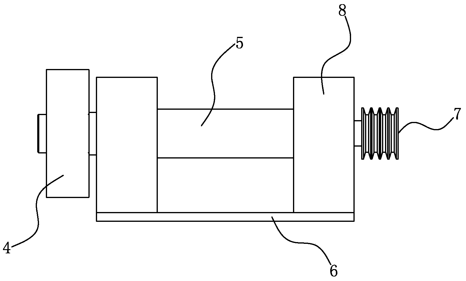
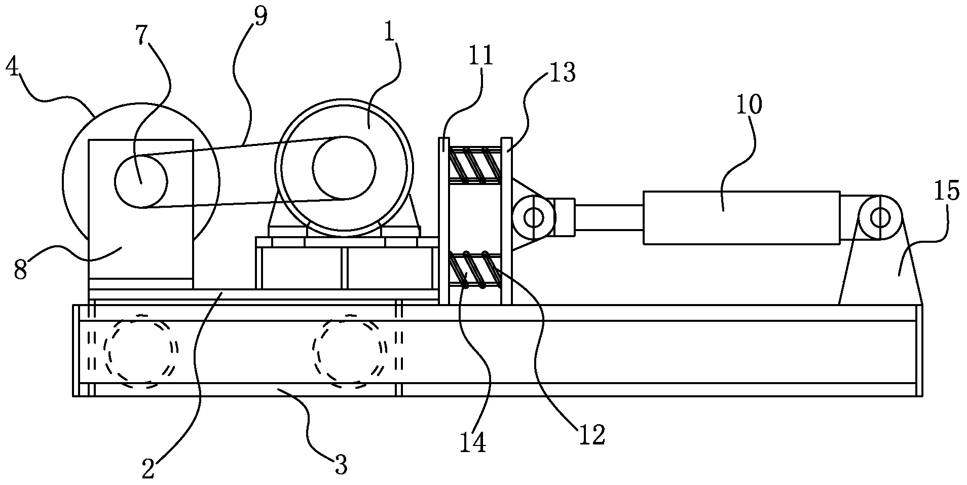
[0011] Such as figure 1 shown, combined with figure 2 As shown, the grinding device for the pipe socket of the present invention includes a grinding machine, a motor 1, a trolley 2, a track 3 and a driving device, the grinding machine includes a grinding head 4, a transmission shaft 5 and a base plate 6, and the grinding head 4 is fixed on the transmission shaft 5, the other end of the transmission shaft 5 is fixed with a pulley 7, the transmission shaft 5 is installed on the bottom plate 6 through two bearing housings 8, and the output shaft of the motor 1 is connected with the pulley 7 through a belt 9 , the belt 9 is a V-belt. Both the base plate 6 and the motor 1 are fixed on the trolley 2, the lower end of the trolley 2 is provided with rollers, and the rollers are located on the track 3, and the extension direction of the track 3 is perpendicular to the axis of the transmission shaft 5. The driving device is a cylinder 10, and the trolley 2 is also fixedly provided wi...


PUM


Abstract

The invention relates to a device for grinding and cleaning the end face of a pipeline socket, and aims to provide a device for grinding the pipeline socket, wherein the device is low in labor intensity and high in grinding quality. The device comprises a grinding machine, a motor (1), a trolley (2), rails (3) and a driving device. The grinding machine comprises a grinding head (4), a transmission shaft (5) and a bottom plate (6). The grinding head is fixed to the transmission shaft, and a belt pulley (7) is fixed to the other end of the transmission shaft. The transmission shaft is arranged on the bottom plate through a bearing pedestal (8). An output shaft of the motor is connected with the belt pulley through a belt (9). The bottom plate and the motor are both fixed to the trolley. Idler wheels are arranged at the lower end of the trolley and located on the rails. The extending direction of the rails is perpendicular to the axis of the transmission shaft. The driving device is used for driving the trolley to move on the rails.

Description

technical field [0001] The invention relates to a mechanical grinding device, in particular to a device for grinding and cleaning the end face of a pipe socket. Background technique [0002] The socket-type pipe is connected by many pipe sections. One end of each pipe section is a socket, and the other end is a socket. The diameter of the socket end is partially enlarged, and its inner diameter is larger than the outer diameter of the socket end. The socket is inserted into the socket of another pipe section to complete the connection of the two pipe sections. In order to successfully connect two socket-type pipes, the socket end faces of the pipes must be cleaned. At present, the casting pipe industry generally adopts a combination of shot blasting machine shot blasting and manual cleaning with an angle grinder. However, manual cleaning requires a lot of physical strength and is not evenly cleaned. Contents of the invention [0003] The technical problem to be solved by...

Claims


Application Information

Patent Timeline
Patent Type & Authority Applications(China)
IPC IPC(8): B24B7/16
CPCB24B7/16B24B47/14
Inventor 郝广增张知明时文博
Owner XINXING DUCTILE IRON PIPES CO LTD
Why Eureka
Eureka Blog
Learn More