A variable-speed automatic tool-feeding device for a bench drill

A technology of automatic tool feeding and bench drilling, applied in the field of machinery, can solve the problems of unreasonable design of the tool feeding mechanism, inconvenient adjustment of feed amount, high cost of quality requirements, etc., to facilitate automatic tool feeding and processing of various materials, and convenient adjustment Fast, the effect of improving labor production efficiency

Active Publication Date: 2015-12-16
TAIZHOU FEIDA MACHINE TOOL
View PDF5 Cites 0 Cited by
  • Summary
  • Abstract
  • Description
  • Claims
  • Application Information

AI Technical Summary

Problems solved by technology

[0002] The existing table drilling machine feeding mechanism is roughly divided into manual feeding, automatic feeding and single-axis CNC feeding. The disadvantages of the manual feeding mechanism are obvious: 1. Low drilling accuracy; Nowadays, with the increasing labor cost, it is an inevitable trend for enterprises to implement automated production equipment
The single-axis CNC feed mechanism is generally driven by an independent motor and equipped with a motion controller, which can realize fully automatic processing, but correspondingly, the quality requirements of operation and maintenance personnel and the cost of related configurations are relatively high, and the investment cost of enterprises is large.
Automatic feed mechanism, the existing feed mechanism design is unreasonable, the use of belt tower pulley transmission structure not only reduces the number of spindle speed changes, but also inconvenient to adjust the feed during use

Method used


Image

  • A variable-speed automatic tool-feeding device for a bench drill
  • A variable-speed automatic tool-feeding device for a bench drill

Examples


Embodiment Construction

[0014] The following are specific embodiments of the present invention and in conjunction with the accompanying drawings, the technical solutions of the present invention are further described, but the present invention is not limited to these embodiments.

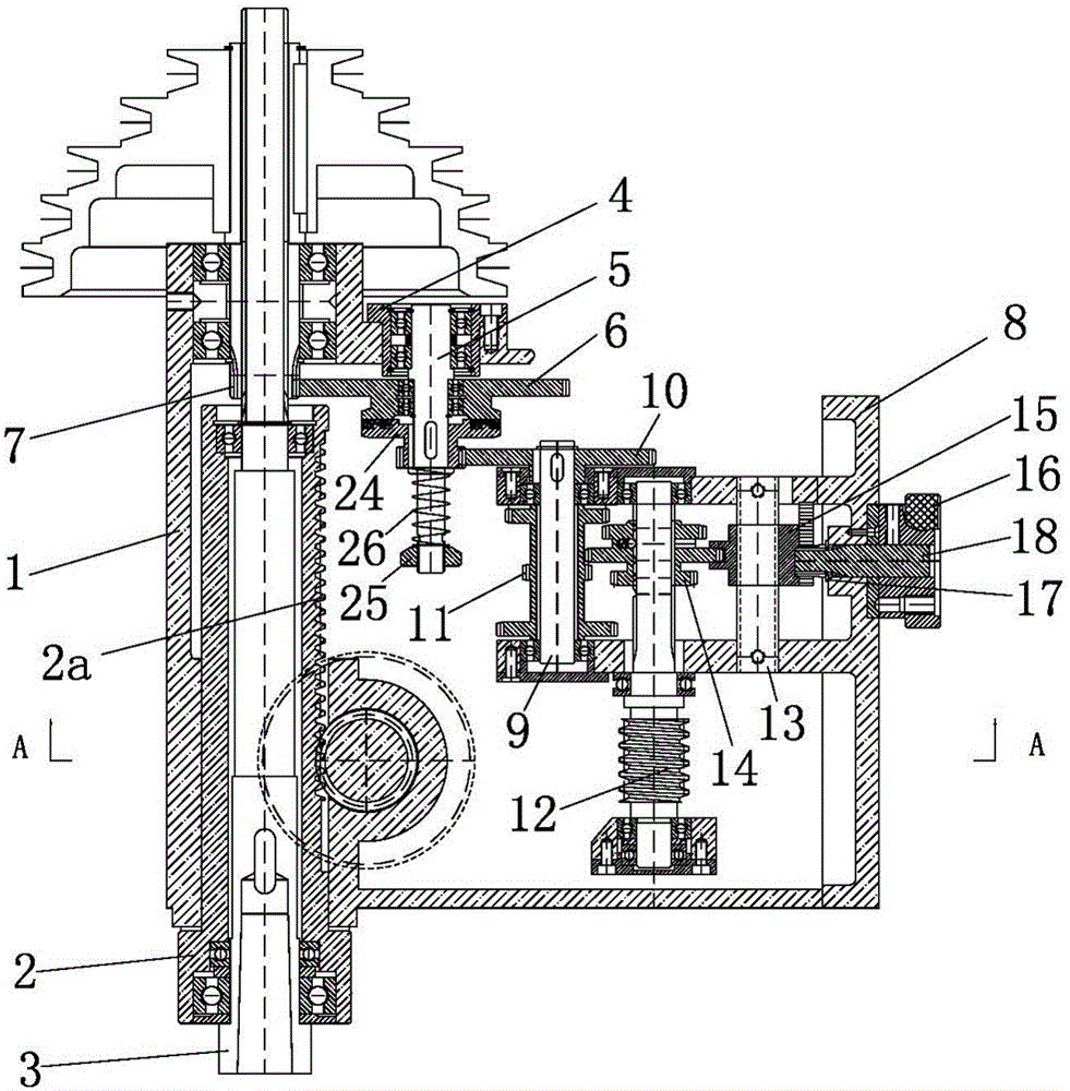
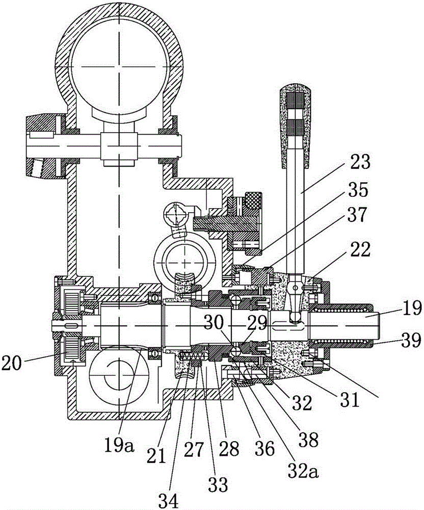
[0015] Such as figure 1 , figure 2 As shown, the variable-speed automatic tool feed device of this bench drill includes a headstock 1, a sleeve 2 and a spindle 3. The sleeve 2 is installed in the headstock 1 and the spindle 3 is installed in the sleeve 2. The headstock 1 is fixed There is a bearing seat 4, and the bearing seat 4 carries a gear fixed shaft 5, a feed fixed gear 6 is fixed on the gear fixed shaft 5, a fixed gear 7 meshing with the feed fixed gear 6 is fixed on the main shaft 3, and the headstock 1 A gear rack 8 is fixedly connected to the gear rack 8. A feed fixed shaft 9 is installed on the gear rack 8. A feed gear 10 and a fixed three-teeth gear 11 are fixed on the feed fixed shaft 9. The feed gear 10 dri...


PUM


Abstract

The invention provides a variable-speed automatic cutter feeding device of a bench drill, and belongs to the technical field of machinery. The problem that the feeding amount of the existing bench drill is inconvenient to adjust is solved. The variable-speed automatic cutter feeding device of the bench drill comprises a bearing block, wherein a gear fixing shaft is carried on the bearing block; a feeding fixing gear is fixed on the gear fixing shaft; a fixing gear which is meshed with the feeding fixing gear is fixed on a spindle; a spindle box is fixedly connected with a gear rack; a feeding fixing shaft is arranged on the gear rack; a feeding gear and a fixed three-connection-tooth gear are fixed on the feeding fixing shaft; the feeding gear drives the gear fixing shaft to rotate through a clutch structure; the gear rack is provided with a worm and a spline shaft which is parallel to the worm; the worm is fixedly connected with a sliding three-connection-tooth gear which is meshed with the fixed three-connection-tooth gear; the spline shaft is provided with a speed-changing shifting fork which is connected with the sliding three-connection-tooth gear; and a gear shaft which is meshed with the speed-changing shifting fork is fixed on the gear rack. The variable-speed automatic cutter feeding device of the bench drill has the advantages of convenience in adjustment, high machining precision and the like.

Description

technical field [0001] The invention belongs to the technical field of machinery, and relates to a bench drill, in particular to a variable-speed automatic tool-feeding device for the bench drill. Background technique [0002] The existing table drilling machine feeding mechanism is roughly divided into manual feeding, automatic feeding and single-axis CNC feeding. The disadvantages of the manual feeding mechanism are obvious: 1. Low drilling accuracy; Nowadays, with the increasing labor cost, it is an inevitable trend for enterprises to implement automated production equipment. The single-axis CNC feed mechanism is generally driven by an independent motor and equipped with a motion controller, which can realize fully automatic processing, but correspondingly, the quality requirements of operation and maintenance personnel and the cost of related configurations are relatively high, and the investment cost of enterprises is large. . For the automatic feed mechanism, the des...

Claims


Application Information

Patent Timeline
Patent Type & Authority Patents(China)
IPC IPC(8): B23B47/18
CPCB23Q5/32
Inventor 李呈峰
Owner TAIZHOU FEIDA MACHINE TOOL
Why Eureka
Try Eureka