Volatile gas treatment system and method thereof
A volatile gas and treatment system technology, applied in the direction of separation methods, chemical instruments and methods, combined devices, etc., can solve problems such as secondary pollution, bonding cannot work continuously, and no effective treatment methods, etc., to achieve reasonable design effects
- Summary
- Abstract
- Description
- Claims
- Application Information
AI Technical Summary
Problems solved by technology
Method used
Image
Examples
Embodiment 1
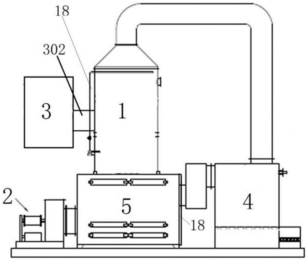
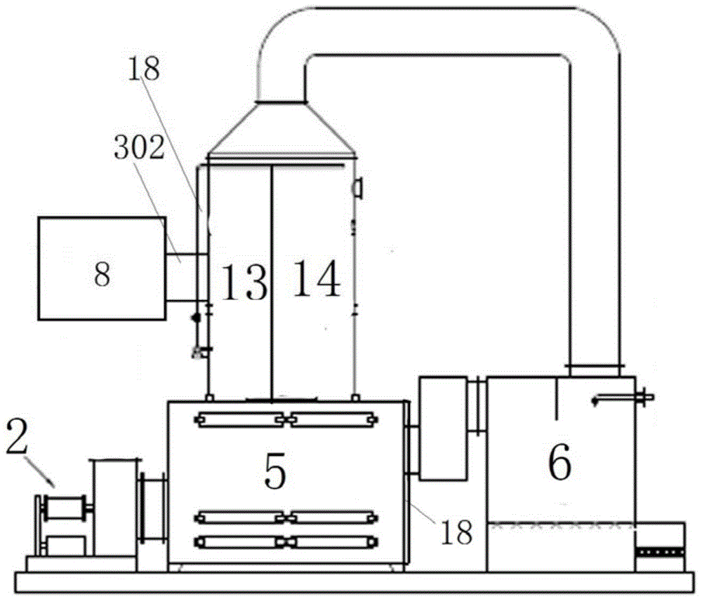
[0089] like figure 1 and figure 2 As shown, a volatile gas treatment system, the volatile gas treatment system includes a volatile gas treatment device 1 and an exhaust device 2;
[0090] The volatile gas treatment system also includes a closed volatile gas generation area 3;
[0091] The volatile gas generating area 3 is provided with a gas outlet, and the volatile gas processing device 1 is provided with an air inlet and a gas outlet;
[0092] The gas outlet of the volatile gas generating area 3 is connected to the air inlet of the volatile gas processing device 1; the air inlet of the volatile gas processing device 1 is provided with a particle filter 18; the volatile gas The gas outlet of the inert gas treatment device 1 is connected with the exhaust device 2 through a pipeline;
[0093] A gas secondary purification device 4 and a drying tower 5 are also arranged between the volatile gas processing device 1 and the exhaust device 2;
[0094]The gas secondary purificat...
Embodiment 2
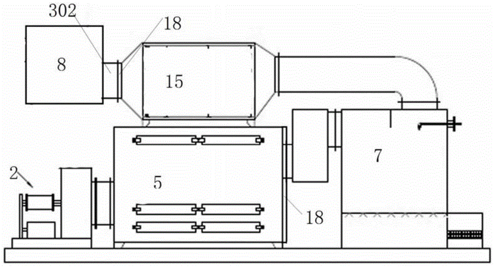
[0128] like image 3 As shown, a volatile gas treatment system is characterized in that: the volatile gas treatment system includes an activated carbon adsorption device 15 and an exhaust device 2;
[0129] The volatile gas treatment system also includes a closed painting room 8; the air inlet of the activated carbon adsorption device 15 is provided with a particle filter 18;
[0130] The painting room 8 is provided with an air outlet, and the activated carbon adsorption device 15 is provided with an air inlet and an air outlet;
[0131] The air outlet of the painting room 8 is connected with the air inlet of the activated carbon adsorption device 15; the air outlet of the activated carbon adsorption device 15 is connected with the exhaust device 2 through a pipeline;
[0132] A water curtain tower 6 is also arranged between the activated carbon adsorption device 15 and the exhaust device 2; the air inlet of the drying tower 5 is provided with a particle filter 18, and the wa...
Embodiment 3
[0154] like Figure 4 As shown, a volatile gas treatment system is characterized in that: the volatile gas treatment system includes a gas phase oxidation treatment device 16 and an exhaust device 2;
[0155] The volatile gas treatment system also includes a closed painting room 8; the air inlet of the gas phase oxidation treatment device 16 is provided with a particle filter 18;
[0156] The painting room 8 is provided with an air outlet, and the gas phase oxidation treatment device 16 is provided with an air inlet and an air outlet;
[0157] The gas outlet of the painting booth 8 is connected to the gas inlet of the gas-phase oxidation treatment device 16; the gas outlet of the gas-phase oxidation treatment device 16 is connected to the exhaust device 2 through a pipeline.
[0158] A spray tower a7 and a drying tower 5 are also arranged between the gas phase oxidation treatment device 16 and the exhaust device 2;
[0159] The spray tower a7 is provided with an air inlet an...
PUM
 Abstract
Description
Claims
Application Information
 - Generate Ideas
- Intellectual Property
- Life Sciences
- Materials
- Tech Scout
- Unparalleled Data Quality
- Higher Quality Content
- 60% Fewer Hallucinations
Browse by: Latest US Patents, China's latest patents, Technical Efficacy Thesaurus, Application Domain, Technology Topic, Popular Technical Reports.
© 2025 PatSnap. All rights reserved.Legal|Privacy policy|Modern Slavery Act Transparency Statement|Sitemap|About US| Contact US: help@patsnap.com


