Eureka AIR delivers breakthrough ideas for toughest innovation challenges, trusted by R&D personnel around the world.

Vane Fluid Transfer Device

A fluid transmission, vane technology, used in parts of pumping devices for elastic fluids, rotary piston pumps, liquid fuel engines, etc. The effect of improving efficiency and reducing difficulty

Inactive Publication Date: 2016-01-06
杨 进煌 +1
View PDF8 Cites 7 Cited by
  • Summary
  • Abstract
  • Description
  • Claims
  • Application Information

AI Technical Summary

Problems solved by technology

[0004] Existing vane pumps drive the centrifugal force of the blades to rotate through the rotor, which promotes the blades to slide outward during the rotation of the rotor, so that the ends of the blades keep in contact with the surrounding walls of the atrioventricular chamber, so that the fluid can be pumped; however, the existing vane pumps are used When pumping low-viscosity fluids such as gas, the tip of the blade and the surrounding wall of the chamber can still maintain contact during operation. When the existing vane pump is used to pump fluids with higher viscosity, it is easy to cause the The phenomenon that the surrounding walls cannot maintain contact to form a gap, which cannot effectively block the adjacent fluid space and affect the fluid pumping efficiency
[0005] Patent documents such as US4212603, US5087183, US5160252, US5181843, and US5558511 respectively disclose the prior art of vane-type fluid transmission devices, mainly forming annular grooves in the stator, and the grooves are concentric with the atrioventricular chambers, and the blades are protruding from the shaft. The pivot is embedded in the groove, and the movement of the blade is guided by the groove; since the rotor and the chamber are eccentric to each other, and the long axis of the blade pivotally embedded in the rotor points to the center of the rotor, the motion track of the mating blade when it is pulled by the rotor , the shape of the inner wall of the chamber presents a complex shape such as an ellipse or an oval, but the complex shape of the inner wall of the chamber greatly increases the difficulty of forming the chamber of the stator; moreover, because the blade is a plate with a thickness In order to avoid the interference between the end of the blade and the inner wall of the atrium on both sides, the end of the blade is sharply reduced in thickness, and the sharp shape of the blade end is likely to cause vibration when the blade end is subjected to the relative force of the fluid The phenomenon further produces running noise, and the vibration phenomenon at the end of the blade is easy to cause local thermal stress at the end of the blade and accelerate the material fatigue at the end of the blade, which affects the service life of the blade

Method used


Image

  • Vane Fluid Transfer Device
  • Vane Fluid Transfer Device
  • Vane Fluid Transfer Device

Examples


Embodiment Construction

[0058] In order to further fully disclose the composition of the present invention and its innovative features, specific feasible embodiments are listed and described below with accompanying drawings.

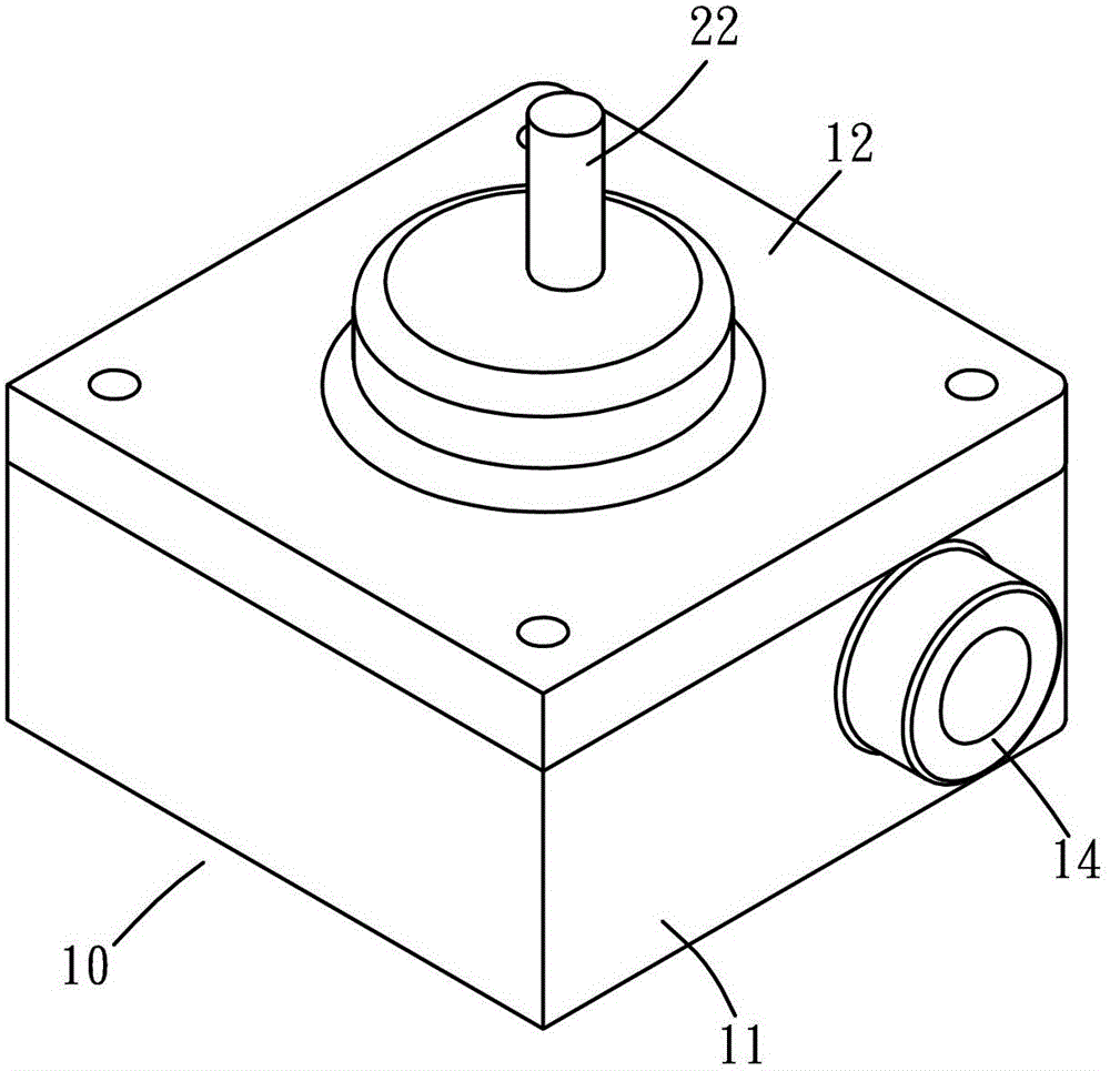
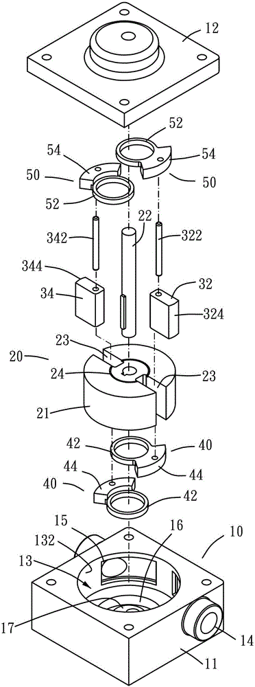
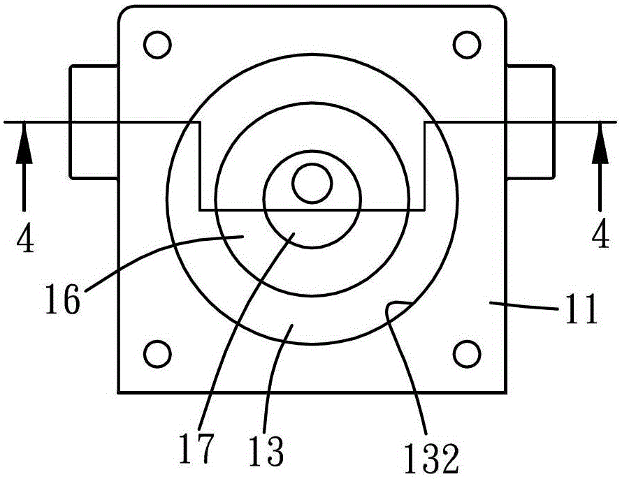
[0059] Such as figure 1 and figure 2 As shown, Embodiment 1 of the vane type fluid transmission device of the present invention includes a stator 10, a rotor 20, two vanes (32, 34), two first linings 40 and two second linings 50, wherein , the stator 10 is mainly composed of a base 11 and a cover 12, a gasket (not shown) can be further interposed between the base 11 and the cover 12, and several bolts ( (not shown in the figure) connect the base 11 and the cover 12 in series, the gasket and the bolt are all existing components familiar to those in the relevant technical field, and will not be described in detail; please cooperate image 3 and Figure 4 As shown, a chamber 13 is formed inside the stator 10, the inner wall 132 of the chamber 13 is circular, and the stator 10 ...


PUM


Abstract

A vane type fluid transmission device, comprising a stator (10), a rotor (20), at least one vane (34), at least one first lining (40) and at least one second lining (50), wherein the stator (10) A room (13) is formed inside, and the room communicates with the outside through a flow channel; the rotor (20) includes a body (21) and a main shaft (22), and the main shaft (22) is connected to the main body (21). The body (21) is eccentrically arranged in the chamber (13), and the outer periphery of the body (21) is in tangential contact with the inner wall of the chamber (13). The body (21) has at least one chute (23) along the diameter direction; the blade (34 ) are pivotally embedded in the chute (23), the blades (34) are in contact with the inner wall of the chamber (13), the first and second linings are respectively pivotally embedded in the stator (10), and the first and second linings are respectively connected to the The center of the circle acts as the center, and the blades are pivotally connected with the first and second linings, so that the blades follow the center of the chamber and move back and forth along the chute; the end of the blade in contact with the inner wall of the chamber forms a circle. The arc surface keeps the tip of the vane in tangential contact with the inner wall of the room, thereby improving the efficiency of fluid pumping and transmission, and reducing the difficulty of forming the room by machining the stator.

Description

technical field [0001] The present invention relates to fluid conveying equipment, and more particularly, to a vane type fluid conveying device. Background technique [0002] The vane pump is mainly composed of a stator, a rotor, and one to several blades. Among them, a room is formed inside the stator, and two flow channels are opened in the stator. The space of the room communicates with the outside through each flow channel. The fluid enters and leaves the chamber respectively through each flow channel. The rotor is set in the rotating assembly inside the chamber. The rotation center of the rotor forms an eccentric state with the center of the chamber, and the outer peripheral surface of the rotor contacts the inner wall of the chamber. The rotor matches the blade The number of chutes varies from one to several. The long axis of each chute points to the rotation center of the rotor. Each blade is pivotally embedded in each chute. One end of each blade points to the rotati...

Claims


Application Information

Patent Timeline
Patent Type & Authority Patents(China)
IPC IPC(8): F01C1/344F04C2/344
CPCF01C21/0836F04C2/3442F01C1/344F04C2/165F04C2/3441F04C29/02
Inventor 杨进煌杨顺吉
Owner 杨 进煌
Why Eureka
Eureka Blog
Learn More