
System and method for achieving multi-port radio frequency device measuring based on radio frequency switch matrix

A technology of radio frequency switch matrix and radio frequency device, applied in transmission systems, electrical components, transmitter monitoring and other directions, can solve the problems of high labor intensity, increased production cost, complicated operation, etc., to reduce labor intensity, reduce labor cost, widely Application-wide effects

Inactive Publication Date: 2014-04-09
View PDF3 Cites 18 Cited by
  • Summary
  • Abstract
  • Description
  • Claims
  • Application Information

AI Technical Summary

Problems solved by technology

[0005] (1) Multiple connection tests are required, which is labor-intensive
[0006] (2) Manually operated instrument testing has high requirements for testers
[0007] (3) The operation is cumbersome, prone to misoperation and low production efficiency
[0009] (1) It can only meet the test of four-port and eight-port devices, and it is difficult to meet the test of all multi-port devices
[0010] (2) The instrument is expensive, resulting in a significant increase in production costs
[0011] (3) Manually operate the instrument for testing, which requires high requirements for testers
[0012] (4) The operation is cumbersome, prone to misoperation and low production efficiency

Method used


Image

  • System and method for achieving multi-port radio frequency device measuring based on radio frequency switch matrix
  • System and method for achieving multi-port radio frequency device measuring based on radio frequency switch matrix

Examples


Embodiment Construction

[0037] In order to be able to describe the technical content of the present invention more clearly, further description will be given below in conjunction with specific embodiments.

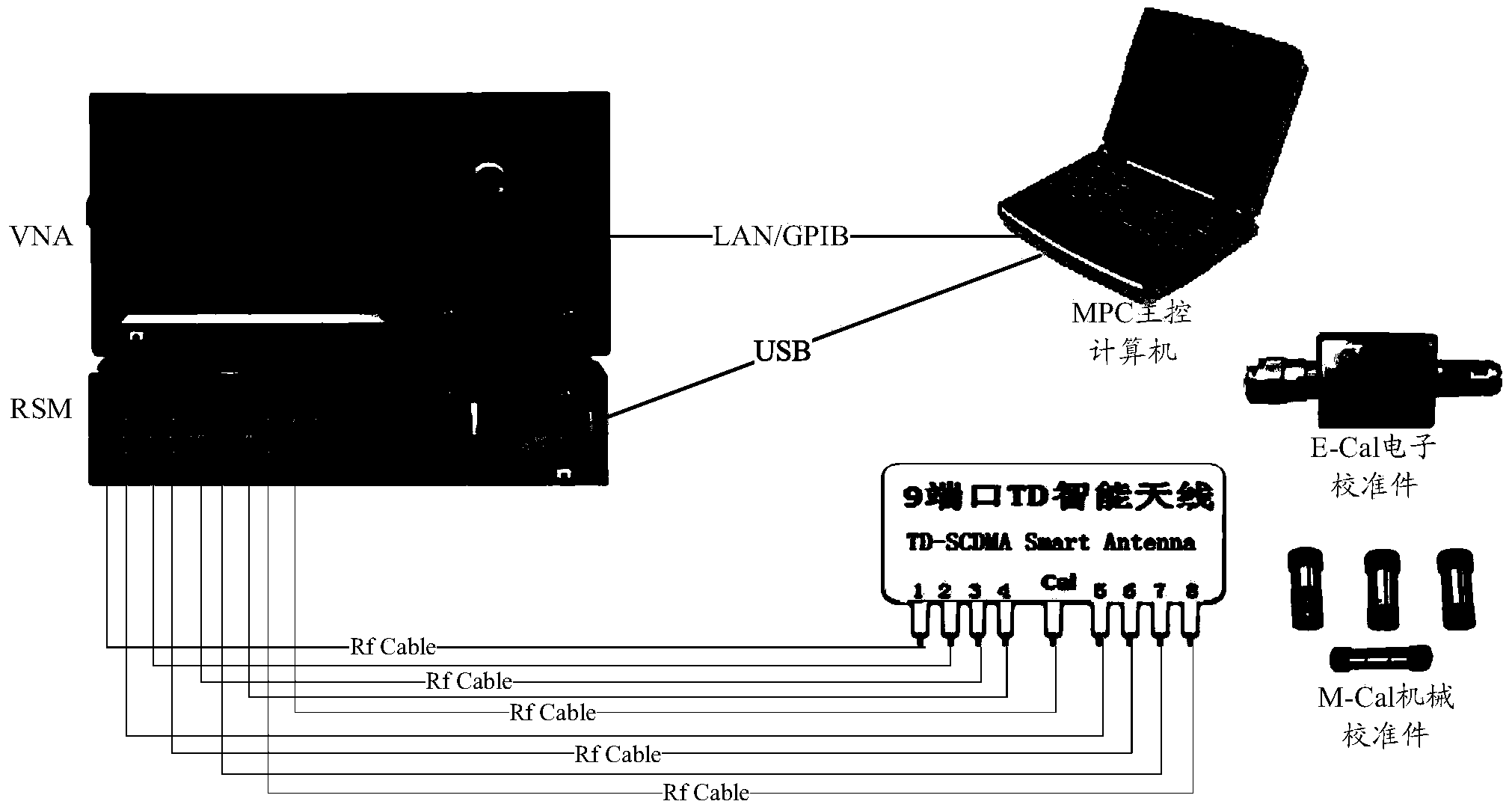
[0038] Hereinafter, the technical solution will be described by taking a 9-port TD smart antenna as an example.

[0039] Such as figure 1 As shown, the 9-port TD (time division synchronization) smart antenna automatic test system includes the following components:

[0040] VNA (Vector Network Analyzer) two-port vector network analyzer.

[0041] RSM (Rf Switch Matrix) radio frequency switch matrix.

[0042] MPC (Main PC) main control computer.

[0043] E-Cal electronic calibration parts or M-Cal mechanical calibration parts.

[0044] The 9-port TD smart antenna needs to test the standing wave of each port, the isolation between adjacent antenna ports, the amplitude and phase between the antenna port and the calibration port, up to more than 50 test values. Connect the antenna port and calibration port of the...


PUM


Abstract

The invention relates to a system and method for achieving multi-port radio frequency device measuring based on a radio frequency switch matrix. The system comprises vector network analyzers, the radio frequency switch matrix and a main control computer. The vector network analyzers are used for measuring a multi-port radio frequency device. The radio frequency switch matrix is used for being connected with the vector network analyzers and the multi-port radio frequency device. The main control computer is used for controlling the vector network analyzers to measure the multi-port radio frequency device automatically. According to the system and method for achieving multi-port radio frequency device measuring based on the radio frequency switch matrix, automatic measuring of the multi-port radio frequency device is achieved based on the radio frequency switch matrix and the two port vector network analyzers, a measured piece is connected at one time, measuring of all S-parameter port indexes of the measured piece is automatically completed, no technical requirements for testing personnel exist, labor cost is lowered, testing time is shortened manifold, labor intensity is lowered, production efficiency is improved, and the wide application range is achieved.

Description

Technical field [0001] The present invention relates to the field of wireless communication technology, in particular to the field of radio frequency device measurement, and specifically refers to a system and method for realizing multi-port radio frequency device measurement based on a radio frequency switch matrix. Background technique [0002] With the rapid development of mobile communication, the coexistence and convergence of 2G, 3G, and 4G have emerged. Therefore, the multi-standard and multi-band situation of mobile communication networks will exist for a long time, resulting in the complexity of mobile communication network equipment The radio frequency components and radio frequency component ports that make up the mobile communication network are getting higher and higher, and the inspection and testing of the S-parameter indicators of radio frequency devices are becoming more and more complicated. Relying on the traditional two-port vector network analyzer, a lot of T...

Claims


Application Information

Patent Timeline
IPC IPC(8): H04B17/00H04B17/15H04B17/29
Inventor 郝富年陈向民陈爽
Learn More