Method and apparatus for diagnosing a fault of a memory

A fault diagnosis device and fault diagnosis technology, applied in the direction of static memory, instrument, etc., can solve the problem of increased fault diagnosis time

Active Publication Date: 2014-04-09
KK TOSHIBA
View PDF4 Cites 3 Cited by
  • Summary
  • Abstract
  • Description
  • Claims
  • Application Information

AI Technical Summary

Problems solved by technology

[0007] This method can detect the coupling failure of the entire memory area, but because the number of writes and reads (read / write) of the memory is proportional to the square of the memory size, the fault diagnosis time will increase rapidly when the memory capacity of the diagnostic object becomes larger. big problem

Method used


Image

  • Method and apparatus for diagnosing a fault of a memory
  • Method and apparatus for diagnosing a fault of a memory
  • Method and apparatus for diagnosing a fault of a memory

Examples


no. 1 approach

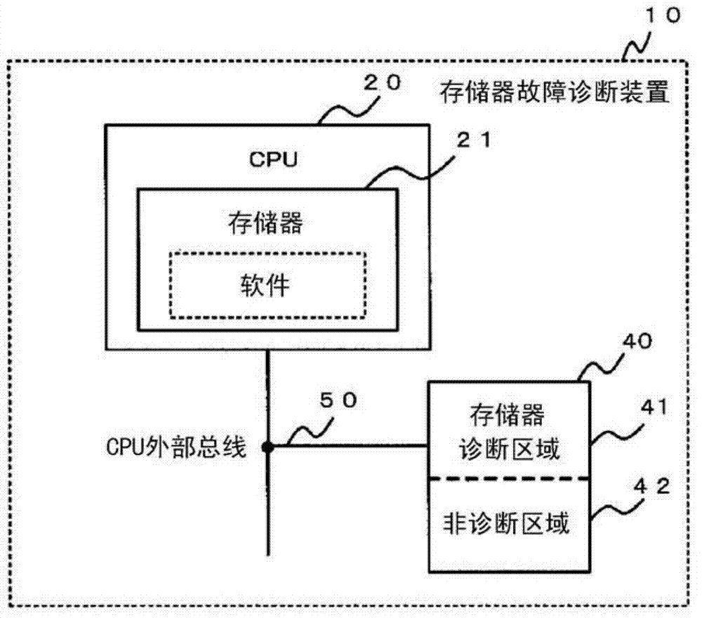
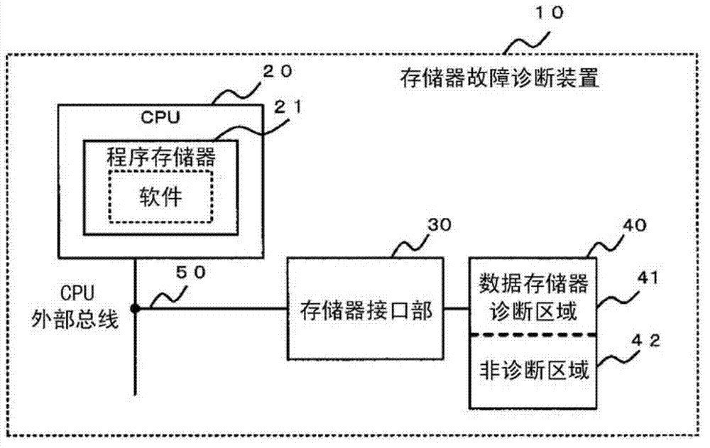
[0047] refer to Figure 1 to Figure 10 , and the first embodiment will be described. figure 1 and figure 2 It is a structural block diagram explaining the first embodiment. The memory fault diagnosis device 10 includes a CPU 20 and a memory 40 connected by a CPU external bus 50 .

[0048] The CPU 20 is provided with a memory 21 storing software including application software (hereinafter referred to as application) for executing applications and memory fault diagnosis software (hereinafter referred to as memory fault diagnosis) for diagnosing a fault in the memory 40 .

[0049] Also, the memory 40 includes a preset diagnostic area 41 to be targeted for memory fault diagnosis and a non-diagnostic area 42 not to be targeted for diagnosis and to be a temporary storage area for fault diagnosis of the diagnostic target area 41 .

[0050] The memory fault diagnosis device 10 may include a CPU core (not shown) and an internal memory, and the CPU core and the internal memory may b...

no. 2 approach

[0151] Below, refer to Figure 11 , the second embodiment of the memory failure detection device according to the present invention will be described. For each part of the second embodiment, the same parts as those of the first embodiment are denoted by the same symbols, and description thereof will be omitted.

[0152] The difference between the second embodiment and the first embodiment is that, regarding the size of the row area, in the first embodiment, the entire column width is taken as the area in the column direction of the memory, but in the second embodiment, for For each row address in the physical address of the memory, only one cell area of ​​the first cell area in the column direction is used as an area, so that the access in the row direction is reduced by the row area size / cell area size in the inter-row area diagnosis quantity.

[0153] In this embodiment, the diagnosis range of the read / write diagnosis in the inter-row area diagnosis is narrowed. However, ...


PUM


Abstract

The invention makes it an object to provide a memory fault diagnostic device and a memory fault diagnostic method which can diagnose a memory fault at a minimum time using an interim time after the execution of an application in a predetermined control cycle, and can minimize a fault diagnostic time for the whole memories in a diagnostic object area. An area of a memory has a diagnosis area (41) and a non diagnosis area (42), with the diagnosis area divided into a plurality of Row areas which do not overlap each other, and each of the Row areas is divided into a plurality of Cell areas which do not overlap each other. A memory fault diagnostic method has a diagnostic step in a Row area to diagnose between Cell areas with respect to all the combinations of a set of Cell areas in the Row area, and a diagnostic step between Row areas to diagnose between Row areas with respect to all the combinations of a set of Row areas in the diagnosis area. A Row area size is determined to be a size in which a time of the diagnosis in a Row area becomes equal to a time of the diagnosis between Row areas.

Description

technical field [0001] Embodiments of the present invention relate to a memory fault diagnosis device and a memory fault diagnosis method. Background technique [0002] For example, in a safety instrumentation system such as a plant that requires high safety, it is necessary to perform fault diagnosis on the memory of the control device that controls the system. [0003] Since the safety instrumentation system requires long-term continuous operation without restarting in units of years, it is necessary to perform fault diagnosis of the memory not only when the system is started, but also during operation. [0004] Generally speaking, in the failure of the memory that becomes the target of fault diagnosis, in addition to the read / write (Read / Write) error of one memory cell, there is also a problem that when a certain memory cell is read / written, the values ​​of other memory cells are changed. Varying coupling fails. [0005] The fault diagnosis algorithm for the coupling fa...

Claims


Application Information

Patent Timeline
Patent Type & Authority Applications(China)
IPC IPC(8): G11C29/08
CPCG11C29/56008G11C29/10G11C2029/5604
Inventor 中谷博司大西直哉天木智鲛田芳富登古诚
Owner KK TOSHIBA
Why Eureka
Try Eureka