
Structure and method for being self-adapted to Ethernet gigabit optical module and electrical module for COMBO interface

A technology of optical modules and electrical modules, applied in electrical components, data exchange networks, digital transmission systems, etc., to achieve the effect of saving panel space and a high degree of automation

Inactive Publication Date: 2014-04-02
PHICOMM (SHANGHAI) CO LTD
View PDF4 Cites 13 Cited by
  • Summary
  • Abstract
  • Description
  • Claims
  • Application Information

AI Technical Summary

Problems solved by technology

However, in actual use, technicians need to judge on the spot whether the SFP interface is connected to an optical module or an electrical module, and manually configure the main switch chip to work normally.

Method used


Image

  • Structure and method for being self-adapted to Ethernet gigabit optical module and electrical module for COMBO interface
  • Structure and method for being self-adapted to Ethernet gigabit optical module and electrical module for COMBO interface
  • Structure and method for being self-adapted to Ethernet gigabit optical module and electrical module for COMBO interface

Examples


Embodiment Construction

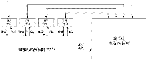
[0026] The structure and method of the COMBO interface self-adaptive Ethernet gigabit optical module and electrical module in the present invention, by setting the FPGA (programmable logic device) to automatically determine whether the optical module or the electrical module is connected to the SFP interface of the main switching chip SWITCH After identification, the FPGA directly automatically configures the interface mode of the main switch chip to SERDES mode or SGMII mode to ensure that it can work normally in both cases.

[0027] Such as image 3 As shown, several I2C interfaces of the FPGA are correspondingly connected to several SFP interfaces (four in the figure) of the main switch chip, and the FPGA detects whether there is a module on the corresponding SFP interface. Taking a SFP optical module FTM9712S-SL20G as an example, its circuit wiring is as follows: Figure 4 As shown, the MOD-DEF1 and MOD-DEF2 ports of the optical module socket are correspondingly connected...


PUM


Abstract

The invention relates to a structure and a method for being self-adapted to an Ethernet gigabit optical module and an electrical module for a COMBO interface. By means of a real-time clock, an FPGA (field programmable gate array) monitors the level changes of in-place signals on an SFP (Small Footprint Package) interface of a master switch chip to judge whether a module is in place in the SFP interface; when the module is monitored in place, the FPGA accesses the EEPROM (electrically erasable programmable read-only memory) of the module connected with the SFP interface via the MASTER mode of an I2C interface to obtain the type information of the module and judge whether the current connected module is the electrical module or the optical module; after obtaining the type information of the module, the FPGA then configures the interface mode of the master switch chip via an MDC / MDIO (Management Data Clock / Management Data Input / Output) interface, i.e., when the connected module is identified as the optical module, the interface mode is configured into an SERDES (Serializer / Deserializer) mode, and when the connected module is identified as the electrical module, the interface mode is configured into an SGMII (Serial Gigabit Media Independent Interface) mode. In the invention, only the SFP interface is set, which is favorable for the miniaturization design of an EPONOLT device; the automation degree of the device is high, and the field or remote support of technicians is not needed.

Description

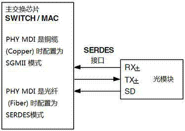
technical field [0001] The invention relates to the field of network equipment, in particular to a structure and method of a COMBO interface adaptive Ethernet gigabit optical module and an electrical module. Background technique [0002] For the uplink Ethernet COMBO interface of most current EPON (Ethernet Passive Optical Network) OLT (Optical Line Terminal) box devices, such as figure 1 As shown, generally the main switching chip SWITCH / MAC is connected to the external PHY (physical layer) chip, and the SFP (Small Footprint Package) interface is physically separated from the RJ45 interface. The SFP interface is only used to connect to the 1000M optical module, and the RJ45 interface It is only used to connect 10 / 100 / 1000M electrical modules, but the SFP interface and RJ45 interface cannot work at the same time. When the RJ45 interface is used, the main switch chip is configured in the electrical module mode (SGMII mode); when the SFP interface is used, it is configured in...

Claims


Application Information

Patent Timeline
IPC IPC(8): H04L12/935H04L49/111
Inventor 甘文斌
Owner PHICOMM (SHANGHAI) CO LTD
Learn More