An isolated bidirectional dc-dc converter
A DC-DC and converter technology, applied in the field of isolated bidirectional DC-DC converters, can solve the problems of the control effect not meeting the requirements, sacrificing the power transmission capability or soft switching characteristics of the converter, etc.
- Summary
- Abstract
- Description
- Claims
- Application Information
AI Technical Summary
Problems solved by technology
Method used
Image

Examples
Embodiment 1
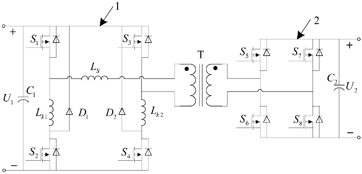
[0055] Embodiment 1: first and second inductance L k1 , L k2 The other end is connected to the busbar as the first structure, when the energy from U 1 Lateral U 2 Each switching mode during side transmission, one cycle can be divided into 6 switching modes, among which the first 3 switching modes and the last 3 switching modes are semi-circularly symmetrical, so only the first 3 switching modes need to be analyzed. Can. where the primary side regulator capacitor C 1 The voltage across the terminal is U 1 , the secondary side regulator capacitor C 2 The voltage across the terminal is U 2 .
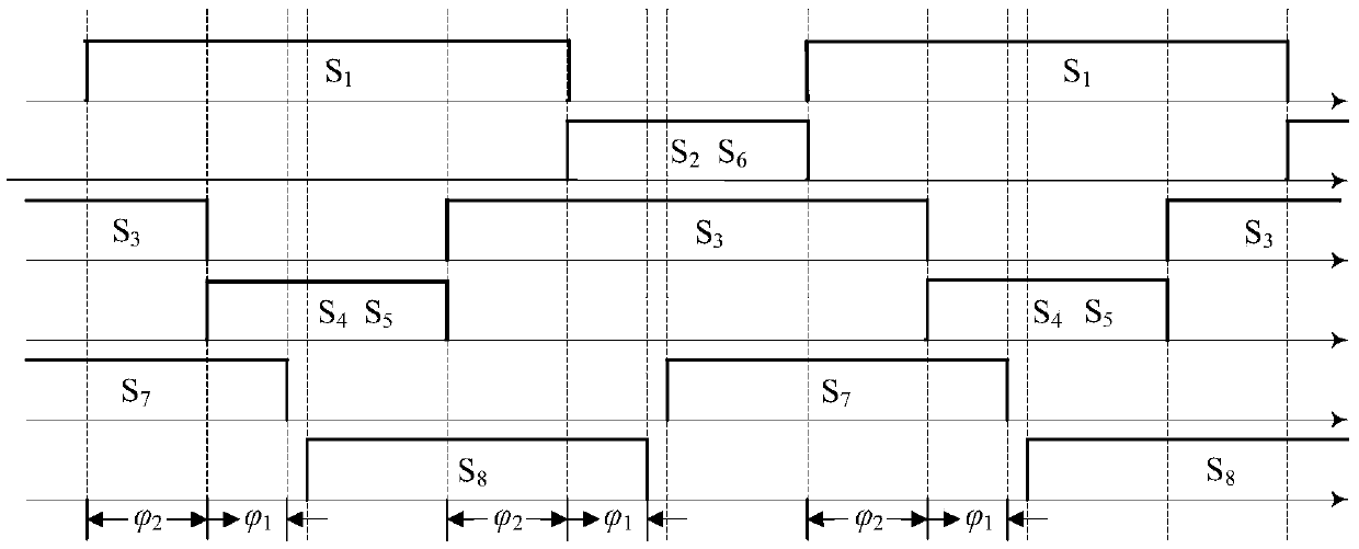
[0056] In this example, if image 3 As shown, the first power switch S 1 and the second power switch S 2 The driving pulse is complementary, the first power switch S 1 The drive pulse width is always greater than the second power switch S 2 the drive pulse width. The third power switch tube S 3 and the fourth power switch S 4 The driving pulse is complementary, the third powe...
Embodiment 2
[0060] Embodiment 2: first and second inductance L k1 , L k2 The other end is connected to the busbar as the first structure, when the energy from U 2 Lateral U 1 Each switching mode during side transmission, one cycle can be divided into 6 switching modes, among which the first 3 switching modes and the last 3 switching modes are semi-circularly symmetrical, so only the first 3 switching modes need to be analyzed. Can. Primary side regulator capacitor C 1 The voltage across the terminal is U 1 , the secondary side regulator capacitor C 2 The voltage across the terminal is U 2 .
[0061] In this example, if Figure 7 As shown, the first power switch S 1 , the third power switch tube S 3 Always in off state, no need to provide drive pulse. Fifth power switch tube S 5 , the sixth power switch tube S 6 The driving pulses are complementary, the pulse widths are equal and there is a dead time; the seventh power switch tube S 7 , the eighth power switch tube S 8 The d...
Embodiment 3
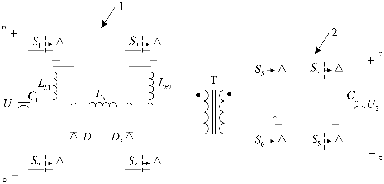
[0066] Embodiment 3: first and second inductance L k1 , L k2 The other end is connected to the busbar as the second structure, when the energy is from U 1 Lateral U 2 Each switching mode during side transmission, one cycle can be divided into 6 switching modes, among which the first 3 switching modes and the last 3 switching modes are semi-circularly symmetrical, so only the first 3 switching modes need to be analyzed. Can. Primary side regulator capacitor C 1 The voltage across the terminal is U 1 , the secondary side regulator capacitor C 2 The voltage across the terminal is U 2 .
[0067] In this example, if Figure 11 As shown, the first power switch S 1 and the second power switch S 2 The driving pulse is complementary, the second power switch S 2 The driving pulse width is always greater than the first power switch S 1 The driving pulse width; the third power switch S 3 and the fourth power switch S 4 The driving pulse is complementary, the fourth power swi...
PUM
 Abstract
Description
Claims
Application Information
 - R&D
- Intellectual Property
- Life Sciences
- Materials
- Tech Scout
- Unparalleled Data Quality
- Higher Quality Content
- 60% Fewer Hallucinations
Browse by: Latest US Patents, China's latest patents, Technical Efficacy Thesaurus, Application Domain, Technology Topic, Popular Technical Reports.
© 2025 PatSnap. All rights reserved.Legal|Privacy policy|Modern Slavery Act Transparency Statement|Sitemap|About US| Contact US: help@patsnap.com