
Method for precisely regulating direction of interference fringes in scanning exposure light path

A scanning exposure and interference fringe technology, applied in the field of spectroscopy, can solve the problems of erasure of grating lines, increase of line width, and reduction of exposure contrast

Active Publication Date: 2014-04-02
CHANGCHUN INST OF OPTICS FINE MECHANICS & PHYSICS CHINESE ACAD OF SCI
View PDF6 Cites 6 Cited by
  • Summary
  • Abstract
  • Description
  • Claims
  • Application Information

AI Technical Summary

Problems solved by technology

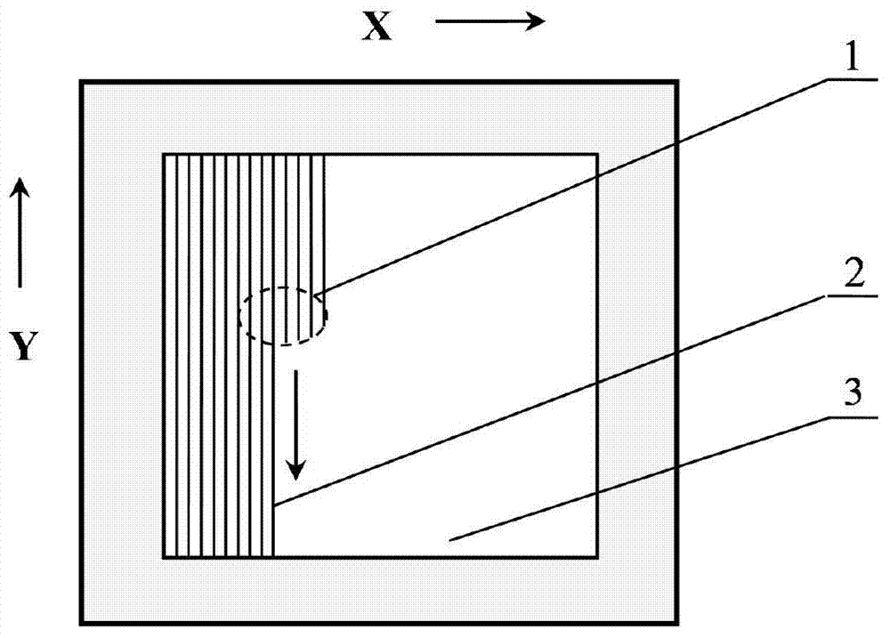
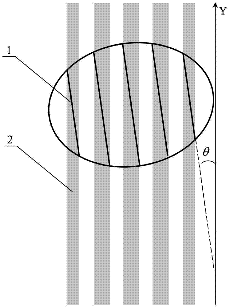
[0004] The present invention aims to solve the problem that in the existing scanning exposure optical path, since the scanning direction is not completely parallel to the interference fringe direction, and there is a certain included angle, the contrast of the exposure is reduced, and the engraved line width increases and the included angle is too large. Provide a method to precisely adjust the direction of interference fringes in the scanning exposure light path

Method used


Image

  • Method for precisely regulating direction of interference fringes in scanning exposure light path
  • Method for precisely regulating direction of interference fringes in scanning exposure light path
  • Method for precisely regulating direction of interference fringes in scanning exposure light path

Examples


specific Embodiment approach 1

[0017] Specific implementation mode 1. Combination Figure 4 and Figure 5 Describe this embodiment, a method for precisely adjusting the direction of interference fringes in the scanning exposure optical path, the method is implemented by the following steps:

[0018] Step 1. Place the reference grating on the two-dimensional motion workbench. Figure 4 It is a top view of the two-dimensional motion table, the grating substrate 3 to be exposed is placed on the two-dimensional motion table 4, and the double guide rails 5 and 6 in the scanning motion direction are perpendicular to the double guide rails 7 and 8 in the stepping motion direction. The workbench 4 is pulled by the linear motor and can move along the scanning direction and the stepping direction respectively. The planar straight line grating with the same period as the grating to be exposed is used as the reference grating, the reference grating 9 is placed on the workbench 4, the surface of the reference grating ...


PUM


Abstract

The invention provides a method for precisely regulating the direction of interference fringes in a scanning exposure light path, relates to the technical field of spectrum, and aims at solving the technical problem to provide the method for regulating the direction of the interference fringes at high precision. In order to solve the technical problems, the method has the technical scheme that a reference grating is placed on a two-dimensional moving work table; a set of scanning exposure light path is prepared; a reflector is regulated so that the exposure light beams respectively meet the Littrow condition; the work table is moved in the scanning direction, the reference grating direction is regulated according to the interference fringe change condition observed on a CCD (charge coupled device); the plane reflector is regulated so that the two light beams coincide at a position PSD (phase-sensitive detector) and an angle PSD. When the method provided by the invention is adopted, the direction of the interference fringes can be precisely regulated, the guarantee is provided for the contrast of a scanning interference field exposure system in the scanning process, and greater actual significance is realized on the manufacture of a scanning exposure holographic grating.

Description

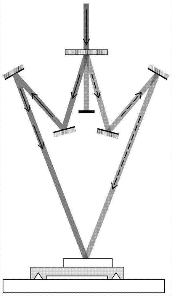
technical field [0001] The invention relates to the field of spectrum technology, in particular to a method for precisely adjusting the direction of interference fringes in the optical path of scanning interference exposure to manufacture holographic gratings. Background technique [0002] There are two main methods for manufacturing holographic gratings: one is the static interference field exposure method, that is, two planar Gaussian beams are superimposed to form linear interference fringes, the interference field and the grating substrate are always kept stationary, and the interference fringes are recorded on the on photoresist. The other is the scanning interference field exposure method. The light emitted from the laser is incident on the optical bearing mechanism placed upright, and the beam propagates along the vertical plane. interference fringes, such as figure 1 As shown, the interference fringes are recorded on the photoresist by the two-dimensional movement ...

Claims


Application Information

Patent Timeline
IPC IPC(8): G02B5/32G02B5/18G03H1/12
Inventor 姜珊巴音贺希格宋莹李文昊潘明忠
Owner CHANGCHUN INST OF OPTICS FINE MECHANICS & PHYSICS CHINESE ACAD OF SCI
Learn More