Eureka AIR delivers breakthrough ideas for toughest innovation challenges, trusted by R&D personnel around the world.

Magnetic group flaw detection method and device for blind rivets

A flaw detection device and technology of pulling rivets, which are applied in the direction of material magnetic variables, etc., can solve the problems of high excitation power, easy burns of workpieces, and failure to meet the needs of rivet flaw detection, etc., to achieve the effect of ensuring sensitivity and low excitation power

Active Publication Date: 2016-04-27
MEISHAN CRRC FASTENING SYST CO LTD
View PDF6 Cites 0 Cited by
  • Summary
  • Abstract
  • Description
  • Claims
  • Application Information

AI Technical Summary

Problems solved by technology

[0003] The rivet group magnetic group flaw detection method and device provided by the present invention solve the problems of the existing single rivet magnetic particle flaw detection technology, such as extremely low flaw detection efficiency, high excitation power, and easy burnt workpieces, so that it cannot meet the requirements of tens of millions of rivets. Issues required for flaw detection

Method used


Image

  • Magnetic group flaw detection method and device for blind rivets
  • Magnetic group flaw detection method and device for blind rivets
  • Magnetic group flaw detection method and device for blind rivets

Examples


Embodiment

[0019] The method for detecting the magnetic grouping of rivet groups in this embodiment includes the following steps:

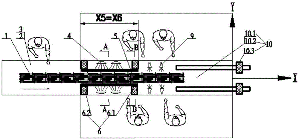
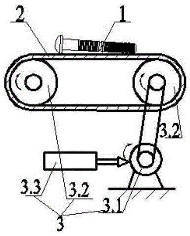
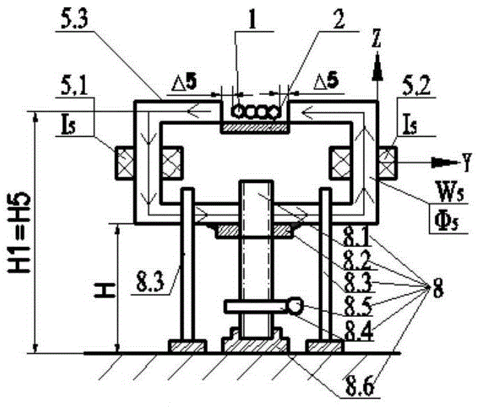
[0020] 1) Add the following process equipment: ①See figure 1 , Set up a stainless steel chain 2 and a stepping conveying mechanism 3 for conveying multiple rivets 1. ①See image 3 , Setting includes opening yoke 5.3, pulling rivet 1, gap Δ 5 Broadband closed circumferential magnetic circuit W formed 5 And the two series-connected circumferential excitation coils 5.1 and 5.2 set on the opening yoke, and the two series-connected axial excitation coils 6.1, 6.2 set on the outer periphery of the rivet, see Figure 7 , There is a thyristor converter circuit 7.1 in the magnetizing power supply 7 and outputs two controllable alternating currents with a phase difference of 120° 5 , Ι 6 They are provided to two sets of excitation coils in the circumferential and axial directions respectively, thereby generating a composite magnetic field Φ. ③See you image 3 , Provide a ...


PUM


Abstract

The invention discloses a pull rivet resultant magnetization grouping flaw detection method and a pull rivet resultant magnetization grouping flaw detection device. The method comprises the following steps: (1) arranging a stepping conveying mechanism, arranging a broadband closed circumferential magnetic path consisting of opened magnet yokes, pull rivets and gaps and circumferential magnet exciting coils, arranging axial magnet exciting coils, providing two controllable alternative current generation resultant magnetic fields, arranging a manual screw nut screw rod lifting mechanism which is fixed at the opened magnetic yokes, and arranging a demagnetization conveying mechanism; (2) manually adjusting the vertical heights of the opened magnet yokes; (3) starting the conveying mechanism, magnetic suspension spraying devices, a magnetization power supply, ultraviolet radiation lamps and the demagnetization conveying mechanism; (4) conveying; (5) spraying the suspension; (6) resultantly magnetizing; (7) inspecting a product; and (8) demagnetizing. When the flaw is detected through controllable automatically conveyed pull rivets, the operation is carried out by multiple operators, 50 to 60 pull rivets can be accomplished within 1 minute, and the efficiency is improved by about 20 times when being compared with that of single pull rivet flaw detection. Through once resultant magnetization, various cracks and fine defects on the surface and near surface of a workpiece can be comprehensively checked at one time, the workpiece is magnetized in a non-contact mode, the magnet excitation capacity is low, the magnet yoke height can be adjusted, and the magnetization sensitivity in magnetizing rivets of different diameters is ensured.

Description

[0001] (1) Technical Field: The present invention relates to a rivet magnetic particle inspection technology, which belongs to the field of product testing, that is, it belongs to the category of testing by measuring the physical properties of materials (G01N) (2) Background technology: [0002] The current magnetic particle inspection technology used to detect pull rivets is explained as follows: Figure 7 , 1) Put a single pull rivet 1 N Clamping in the workpiece clamping device 2 N Up; 2) Start the magnetic powder spray head 3 N , Spray magnetic powder on a single rivet; 3) Start the magnetizing system 4 N , Energize the pull rivet to magnetize; 4) loosen the clamping device 2 N , No longer energize; 5) Perform flaw detection; 6) Pass the demagnetization device 10 N Demagnetize the workpiece. The disadvantages of this process are: ① Manual clamping is used, and only one workpiece can be loaded at a time. The complete inspection process of a single rivet takes about 20 seconds. Ea...

Claims


Application Information

Patent Timeline
Patent Type & Authority Patents(China)
IPC IPC(8): G01N27/84
Inventor 杨江胡方年伏凯刘俊杰王霞罗金成何刚李新荣张荣万永徐誌
Owner MEISHAN CRRC FASTENING SYST CO LTD
Why Eureka
Eureka Blog
Learn More