Tube-in-tube energy-saving lamp

An energy-saving lamp and tube-in-tube technology, which is applied in energy-saving control technology, electric lamp circuit layout, cooling/heating device of lighting devices, etc. It is easy to burn out light-emitting diodes and other problems, so as to improve the heat dissipation effect, increase the luminous efficiency, and reduce the secondary energy consumption.

Inactive Publication Date: 2014-04-02
戴建国
View PDF8 Cites 1 Cited by
  • Summary
  • Abstract
  • Description
  • Claims
  • Application Information

AI Technical Summary

Problems solved by technology

[0004] However, the heat dissipation effect of the tube-in-tube energy-saving lamp in the prior art is not good. When used for a long time, the light-emitting diode is easily burned due to the increase of the temperature inside the tube; and the service life of the tube-in-tube energy-saving lamp in the prior art is not long enough. , the light stability is not very good
In addition, the tube-in-tube energy-saving lamps in the prior art have a large loss of light, so the illuminance is still not enough; moreover, the guide posts in the tube-in-tube energy-saving lamps in the prior art cannot rotate, so that they can only Installation at a specific angle, but sometimes energy-saving lamps are installed on the ceiling, and sometimes on the wall, the guide column of this fixed structure cannot meet the demand

Method used


Image

  • Tube-in-tube energy-saving lamp
  • Tube-in-tube energy-saving lamp
  • Tube-in-tube energy-saving lamp

Examples


Embodiment Construction

[0029] The present invention will be described in further detail below in conjunction with the specific embodiments and the accompanying drawings, but the embodiments of the present invention are not limited thereto.

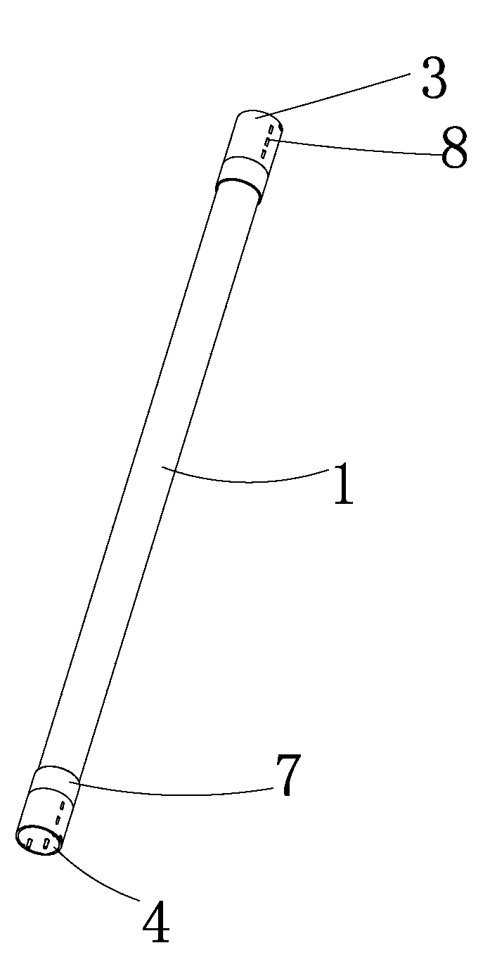
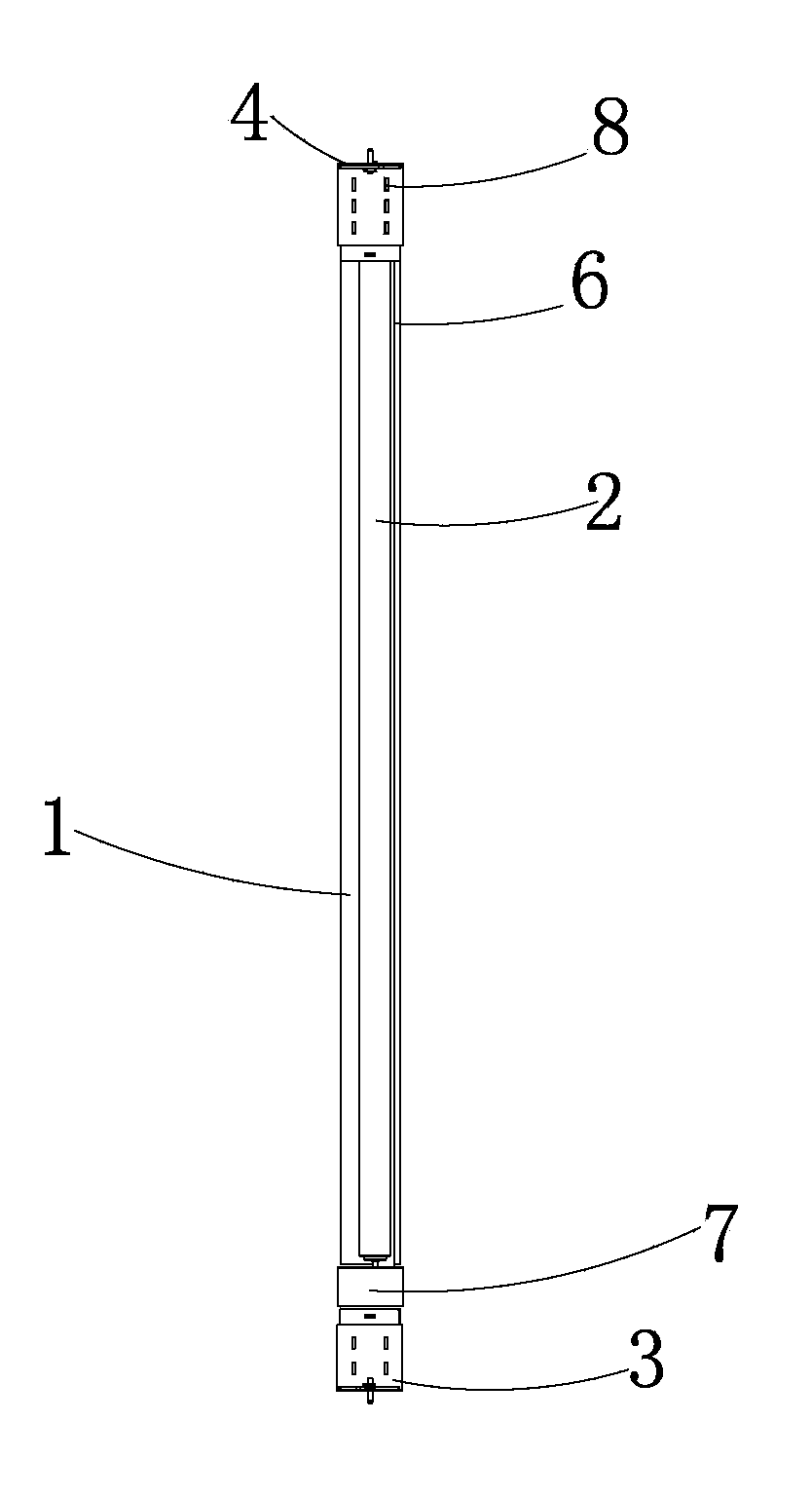
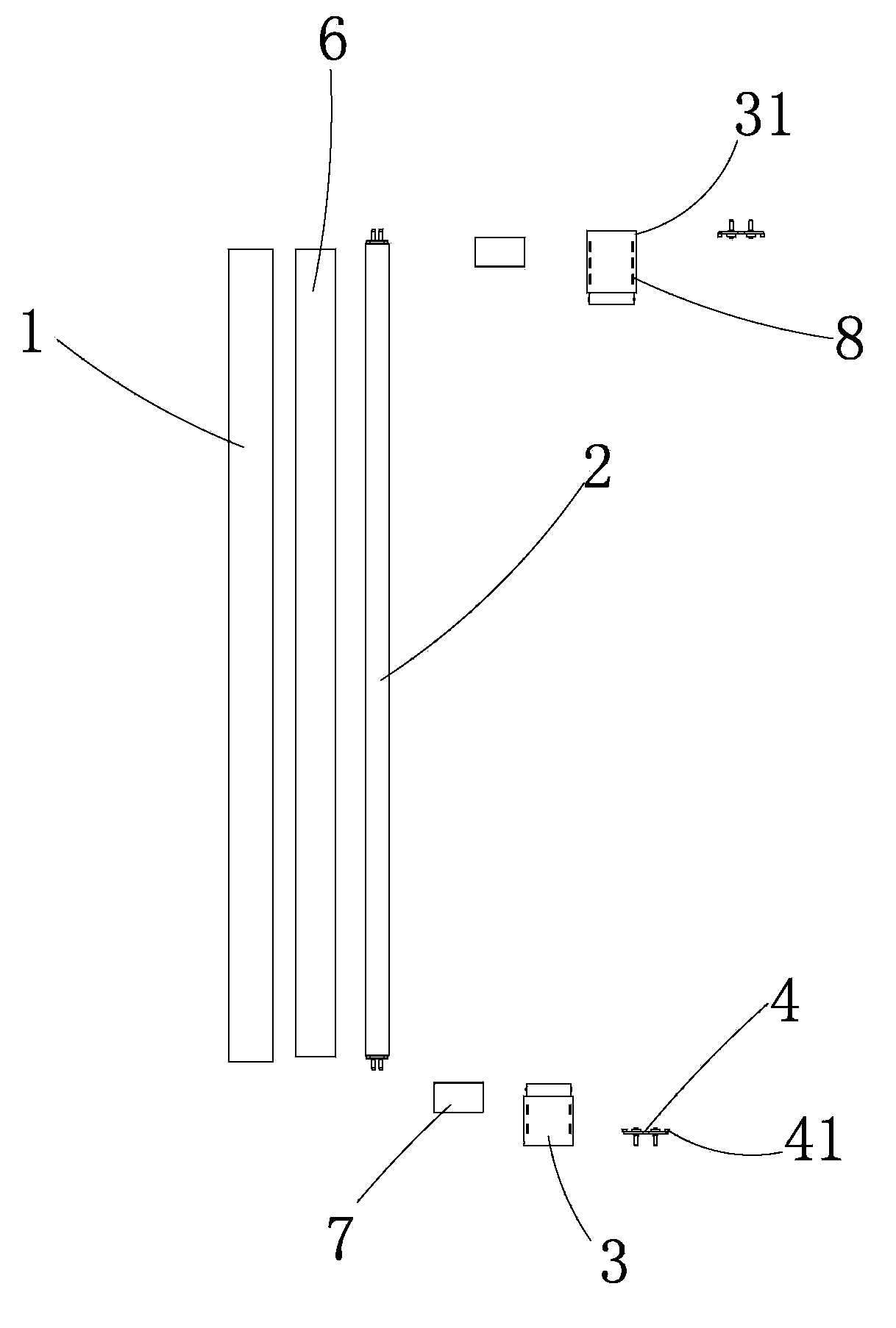
[0030] Such as Figure 1 to Figure 4 As shown, a tube-in-tube energy-saving lamp provided by the present invention includes a transparent glass sleeve 1, a three-primary color light-emitting tube 2, ferrules 3 arranged at both ends of the transparent glass sleeve 1 and guide posts arranged at one end of the ferrule 3 4. A rectifier 5 is arranged in the ferrule 3, a plug 7 is arranged between the transparent glass sleeve 1 and the ferrule 3, and the cross-section of the reflective sheet 6 is in the shape of a semicircle arc, and the three primary color light-emitting tubes 2 are arranged on the transparent Inside the glass casing 1, and the three primary color light-emitting tubes 2 are installed on the side of the plug 7 close to the reflective sheet 6 (that is,...


PUM


Abstract

The invention belongs to the technical field of energy-saving lamps and particularly relates to a tube-in-tube energy-saving lamp. The tube-in-tube energy-saving lamp comprises a transparent glass sleeve, a three-primary-color light emitting tube, clamp sleeves and guide columns. The clamp sleeves are disposed at two ends of the transparent glass sleeve. Each guide column is disposed at one end of the corresponding clamp sleeve. A rectifier is disposed in each clamp sleeve. A plug is disposed between the transparent glass sleeve and each clamp sleeve. Radiating holes are formed in each plug and each clamp sleeve. A rectifying control circuit board is mounted in the rectifier. Two layers of folded reflectors are disposed on the inner wall of the transparent glass sleeve. The three-primary-color light emitting tube is disposed in the transparent glass sleeve and mounted on one side, close to the reflectors, of each plug. Each guide column is fastened to the corresponding clamp sleeve. The tube-in-tube energy-saving lamp has the advantages that by the reflectors disposed in the transparent glass sleeve, the original wasted light can be reflected to the effective lighting range, lighting intensity is increased, efficient conversion of electric energy and optical energy is achieved, energy conservation is achieved, and the lamp is suitable for being mounted in different occasions.

Description

technical field [0001] The invention belongs to the technical field of energy-saving lamps, in particular to a tube-in-tube energy-saving lamp. Background technique [0002] Energy-saving lamps are lamps that use high-brightness white light-emitting diodes as light sources. They have many advantages such as high luminous efficiency, low power consumption, long life, easy control, maintenance-free, safety and environmental protection, etc. It is a new generation of solid cold light source, light color Soft, bright, colorful, low loss, low energy consumption, suitable for long-term lighting in various public places such as homes, shopping malls, banks, hospitals, hotels and restaurants. [0003] Among them, the tube-in-tube energy-saving lamp is a new type of energy-saving product converted from T8 to T5. Using it to replace the traditional inductive T8 fluorescent lamp can save 50-70% of lighting power; and using it to replace the T5 fluorescent lamp can save 40-60% of elect...

Claims


Application Information

Patent Timeline
Patent Type & Authority Applications(China)
IPC IPC(8): F21S2/00F21V7/22F21V29/00H05B37/02F21K9/20F21V29/50F21V29/83F21Y115/10
CPCY02B20/40
Inventor 戴建国
Owner 戴建国
Why Eureka
Try Eureka