A mold clamping mechanism of an injection molding machine driven by a diamond-shaped connecting rod and a double-wire screw

A technology of injection molding machine and thread, which is applied in the field of mold clamping mechanism of injection molding machine, can solve the problems of low template parallelism, unbalanced template force, large template deformation, etc., to improve the quality of injection molding products, short movement cycle, The effect of small deformation

Active Publication Date: 2016-02-24
ZHEJIANG UNIV +1
View PDF2 Cites 0 Cited by
  • Summary
  • Abstract
  • Description
  • Claims
  • Application Information

AI Technical Summary

Problems solved by technology

[0003] Aiming at the defects of the traditional toggle mold clamping mechanism that the template is unbalanced in force, the template is deformed, the friction is large, the energy consumption is high, the wear is heavy, and the parallelism of the template is low, the purpose of the present invention is to provide a diamond-shaped connecting rod double-wire wire The mold clamping mechanism of the injection molding machine driven by the rod adopts the servo motor to drive the double-wire screw. Through the double-wire screw and the nut, the rotational motion is converted into the relative motion of the two nuts, which drives the diamond-shaped linkage mechanism to realize mold opening, Clamping movement and achieving clamping force maintenance

Method used


Image

  • A mold clamping mechanism of an injection molding machine driven by a diamond-shaped connecting rod and a double-wire screw
  • A mold clamping mechanism of an injection molding machine driven by a diamond-shaped connecting rod and a double-wire screw
  • A mold clamping mechanism of an injection molding machine driven by a diamond-shaped connecting rod and a double-wire screw

Examples


Embodiment Construction

[0015] The present invention will be further described below in conjunction with the accompanying drawings and specific embodiments.

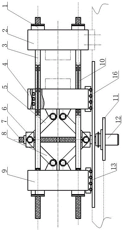
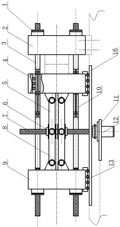
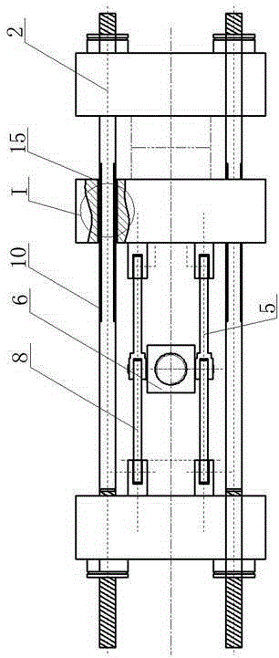
[0016] Such as figure 1 , figure 2 , image 3 As shown, the present invention includes a front template 2, a movable template 4, a rear template 9, four pull rods 3, two left connecting rods 8, two right connecting rods 5, two nuts 6, a double wire lead screw 7, and a servo motor 12. Two sets of roller sets 13, the first guide rail set 10, the short guide rail 11, the second guide rail set 15 and the long guide rail 16; there are tie rod holes on the four corners of the rear template 9, the movable template 4 and the front template 2, and four pull rods 3 After passing through the tie rod holes of the rear formwork 9, the moving formwork 4 and the front formwork 2 in turn, one end of the four tie rods 3 is fixedly connected to the front formwork 2, and the other ends of the four tie rods 3 are fixedly connected to the back formwork 9, and th...


PUM


Abstract

The invention discloses a die-assembling mechanism of an injection molding machine with double lead screw drive by rhombic connecting rods. Four pull rods sequentially pass through pull rod holes of a rear template, a movable template and a front template, one end of each of the four pull rods is fixedly connected with the front template while the other end of each of the four pull rods is fixedly connected with the rear template, the front template is fixed on a frame of the injection molding machine, one ends of first and second left connecting rods are respectively hinged with the rear template, one ends of first and second right connecting rods are respectively hinged with the movable template, a servo motor is supported in a horizontal groove in the centre of a short guide rail of the frame of the injection molding machine and is connected with a double lead screw through a coupler, and rhombic connecting rod mechanisms are formed at both ends of the double lead screw. The end faces of the rear and movable templates are installed on a long guide rail of the frame of the injection molding machine through roller units, respectively. The rhombic connecting rod mechanisms drive the movable template to reciprocate, so that the mechanism has the characteristics of short period of motion, stability of mould clamping force and small deformation of the movable template. The mechanism disclosed by the invention is suitable for die-assembling mechanisms of small and medium-sized injection molding machines for precise mould injection.

Description

technical field [0001] The invention relates to an injection molding machine, in particular to a mold clamping mechanism of an injection molding machine driven by a diamond-shaped connecting rod and a double-wire lead screw. Background technique [0002] At present, the mainstream mold opening and closing mechanism of injection molding machines in the market is still the traditional five-point oblique row double toggle mold clamping mechanism, which is driven by a hydraulic cylinder piston or a servo motor driven screw to push the crosshead, and is connected by a crosshead connecting rod. The toggle mechanism drives the mobile template to reciprocate, realizes the mold opening and closing actions and provides the corresponding clamping force; however, the traditional mold closing mechanism has many defects. First, the toggle mechanism has many parts and the elbow movement is relatively complicated , the elbow movement is easy to lock at the limit position or the movement is ...

Claims


Application Information

Patent Timeline
Patent Type & Authority Patents(China)
IPC IPC(8): B29C45/66
CPCB29C45/661
Inventor 张树有张鹏
Owner ZHEJIANG UNIV
Why Eureka
Try Eureka