Special machine tool for multi-surface mill

A special machine tool and face milling technology, which is applied in the direction of milling machine equipment, milling machine equipment details, metal processing equipment, etc., can solve the problems of difficulty in meeting the requirements of verticality tolerance, time-consuming and labor-intensive processing, and positioning errors, etc., to achieve compact structure and improve processing efficiency , The effect of high milling precision

Inactive Publication Date: 2014-04-02
JIANGSU ZHENJI MACHINERY MFG
View PDF5 Cites 3 Cited by
  • Summary
  • Abstract
  • Description
  • Claims
  • Application Information

AI Technical Summary

Problems solved by technology

[0002] Some machined parts have multiple sides that need to be milled. For example, there are four sides on the inside and outside of the cylinder fork that need to be milled. The traditional processing method is to mill these four sides one by one on an ordinary milling machine. During the processing The fork head of the middle oil cylinder needs to be clamped many times, the processing is time-consuming and laborious, the work efficiency is extremely low, and the repeated positioning and clamping, the positioning error accumulated many times, resulting in the perpendicularity between the four sides of the oil cylinder fork head and the center line of the horizontal pin hole Tolerances are difficult to meet

Method used


Image

  • Special machine tool for multi-surface mill
  • Special machine tool for multi-surface mill
  • Special machine tool for multi-surface mill

Examples


Embodiment Construction

[0014] The present invention will be further described below in conjunction with drawings and embodiments.

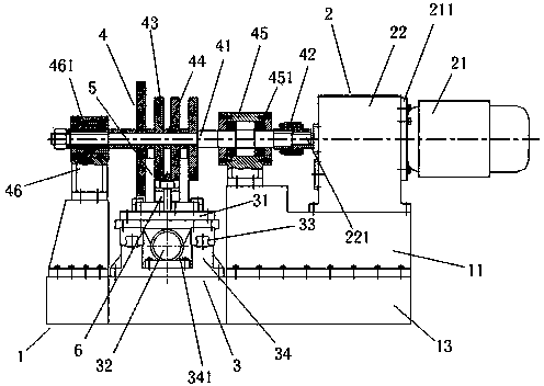
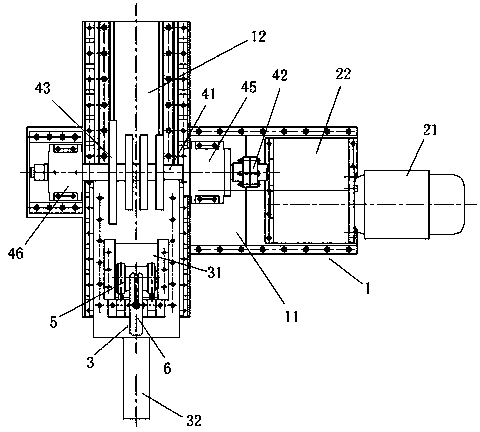
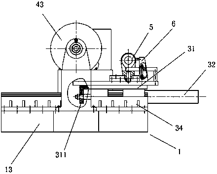
[0015] Such as Figure 1 ~ Figure 3 As shown, the present invention includes a fuselage 1, a power unit 2, a feeding device 3 and a milling cutter device 4. The fuselage 1 is in the shape of a cross and includes a longitudinal base 11 and a transverse base 12 connected as a whole. The longitudinal base 11, the transverse base 12 and the common base 13 on the lower side are fixedly connected as a whole by a plurality of fasteners. The longitudinal base 11, the transverse base 12 and the common base 13 can be welded steel structures, and can also be cast iron or cast steel structures. The present invention is a welded steel structure, which is convenient for a small amount of manufacturing and reduces the manufacturing cycle and cost of wooden molds.

[0016] The power unit 2 is arranged on the right end of the longitudinal base 11, and includes a drive motor 21 and ...


PUM


Abstract

The invention discloses a special machine tool for a multi-surface mill. The special machine tool comprises a machine body, a power device, a feeding device and a milling cutter device, wherein the machine body comprises a longitudinal base and a horizontal base which are integrally connected; the power device is arranged at one end of the longitudinal base and comprises a drive motor and a transmission gear case, and an output shaft of the transmission gear case is fixedly connected with the milling cutter device; the feeding device is arranged at one end of the horizontal base; the milling cutter device comprises a cutter bar and supporting seats arranged at the two ends of the cutter bar; one end of the cutter bar is fixedly connected with the output shaft of the transmission gear case through a shaft coupler; multiple rows of milling cutter disks are arranged in parallel in the middle of the cutter bar at an interval; the two ends of the cutter bar are supported in corresponding bearing seats through bearings respectively. The special machine tool is compact in structure and high in milling precision; the rows of milling cutter disks on the cutter bar are capable of achieving clamping in one time and feeding in one time to finish milling of a plurality of side surfaces, so that the verticality between the side surfaces and central lines of horizontal pin holes of processed parts is guaranteed and the processing efficiency is greatly improved.

Description

technical field [0001] The invention relates to a disc milling machine with multiple milling cutters, in particular to a special milling machine capable of completing multiple side milling processes with only one clamping and one feeding of workpieces, belonging to the technical field of metal cutting machine tools. Background technique [0002] Some machined parts have multiple sides that need to be milled. For example, there are four sides on the inside and outside of the cylinder fork that need to be milled. The traditional processing method is to mill these four sides one by one on an ordinary milling machine. During the processing The fork head of the middle oil cylinder needs to be clamped many times, the processing is time-consuming and laborious, the work efficiency is extremely low, and the repeated positioning and clamping, the positioning error accumulated many times, resulting in the perpendicularity between the four sides of the oil cylinder fork head and the cen...

Claims


Application Information

Patent Timeline
Patent Type & Authority Applications(China)
IPC IPC(8): B23C3/00
Inventor 谭文俊张水祥聂玫
Owner JIANGSU ZHENJI MACHINERY MFG
Why Eureka
Try Eureka