
Windmill rotary vane turning device and wind-powered electricity generation device equipped with same

A windmill rotation and steering device technology, which is applied to wind engines, wind generator components, and wind power generation in the same direction as the wind, can solve problems such as low frequency of use, increased manufacturing costs of wind power generation devices, and increased manufacturing costs. Achieve the effect of cheap structure and retain complete security

Inactive Publication Date: 2014-03-26
MITSUBISHI HEAVY IND LTD
View PDF7 Cites 3 Cited by
  • Summary
  • Abstract
  • Description
  • Claims
  • Application Information

AI Technical Summary

Problems solved by technology

Therefore, the steering device becomes an expensive piece of equipment that is used infrequently in relation to the operating time of the wind power generation device, and this becomes a factor that increases the manufacturing cost of the wind power generation device.
[0012] In addition, in the steering device of Patent Document 1, the driving force of the electric motor is transmitted to the rotating shaft of the speed increaser through a relatively expensive gear mechanism, so this also increases the manufacturing cost.
Furthermore, when the gear mechanism is used to transmit the power of the electric motor to the side of the windmill rotor, when the wind speed is estimated to be low and the windmill rotor is turned over, a strong wind is applied from the windmill rotor when a sudden storm (gale wind) blows. In the case of a large torque fluctuation, the torque fluctuation is transmitted to the electric motor side as it is, which may damage the driving force transmission elements such as the electric motor and gear mechanism

Method used


Image

  • Windmill rotary vane turning device and wind-powered electricity generation device equipped with same
  • Windmill rotary vane turning device and wind-powered electricity generation device equipped with same
  • Windmill rotary vane turning device and wind-powered electricity generation device equipped with same

Examples


Embodiment Construction

[0044] Below, refer to Figure 1 to Figure 8 Embodiments of the present invention will be described.

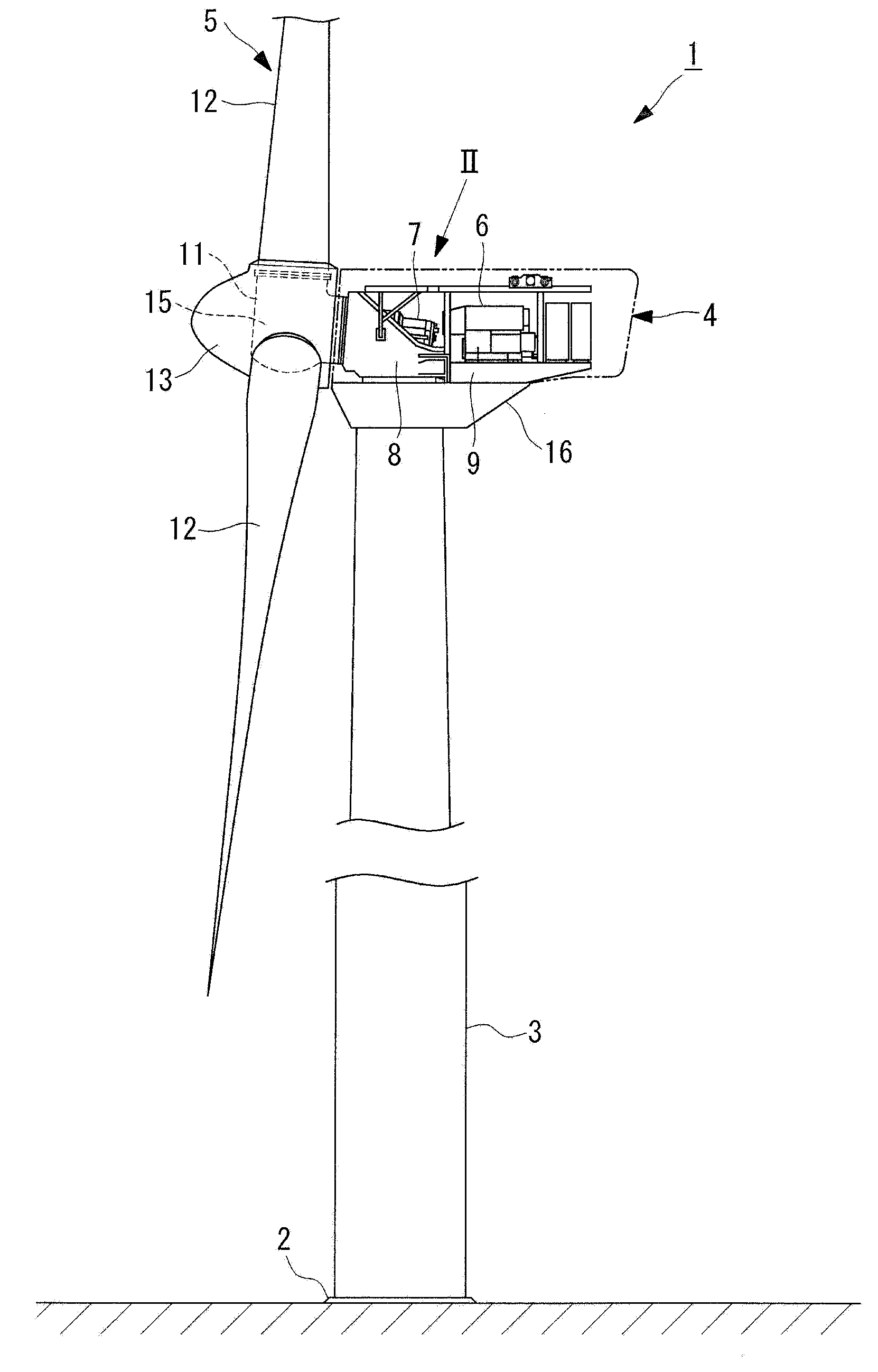
[0045] figure 1 It is a side view showing an example of a wind power generator to which the steering device according to the embodiment of the present invention can be applied. The wind power generation device 1 includes: a tower 3 erected on the upper surface of a reinforced concrete foundation 2 buried in the ground; a pod 4 installed on the upper end of the tower 3; a windmill rotor 5, It is installed in the pod 4 ; the generator 6 and the speed increaser 7 are accommodated inside the pod 4 and generate electricity by the rotation of the windmill rotor blade 5 .

[0046] The speed increaser 7 is housed in a highly rigid steel pod deck 8 at the upper end of the tower 3 together with a main bearing (not shown) that pivotally supports the main shaft of the windmill rotor blade 5 . It is pivotally supported so that it can rotate freely. In addition, a generator installatio...


PUM


Abstract

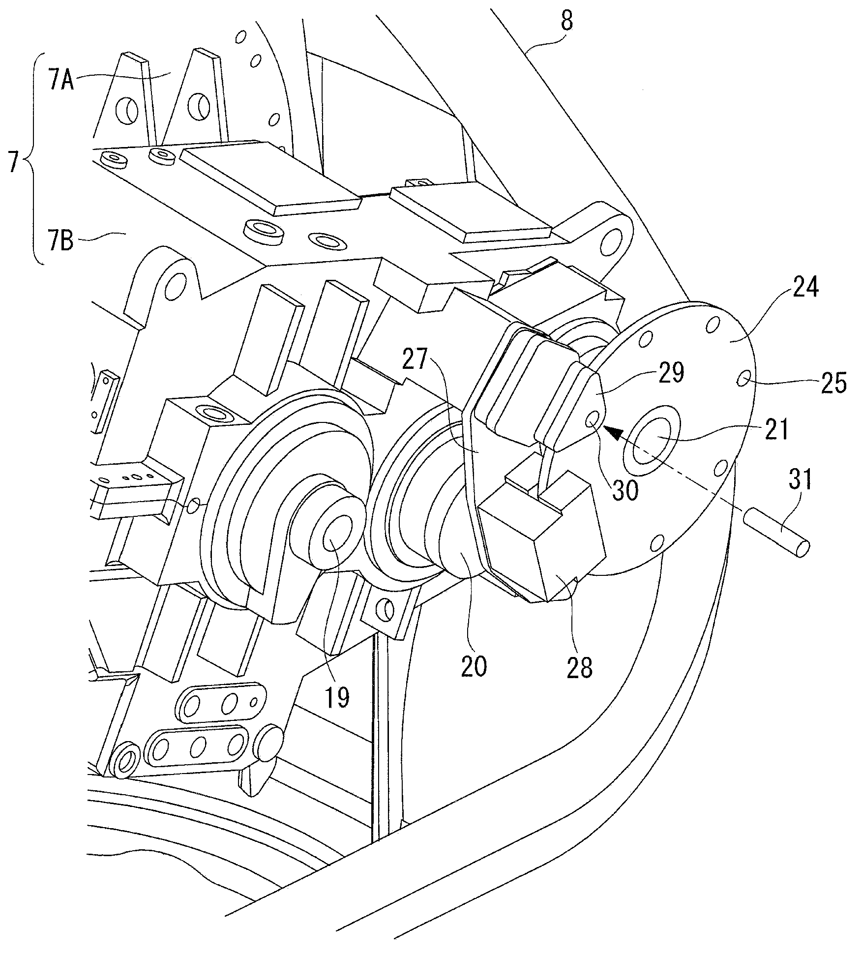
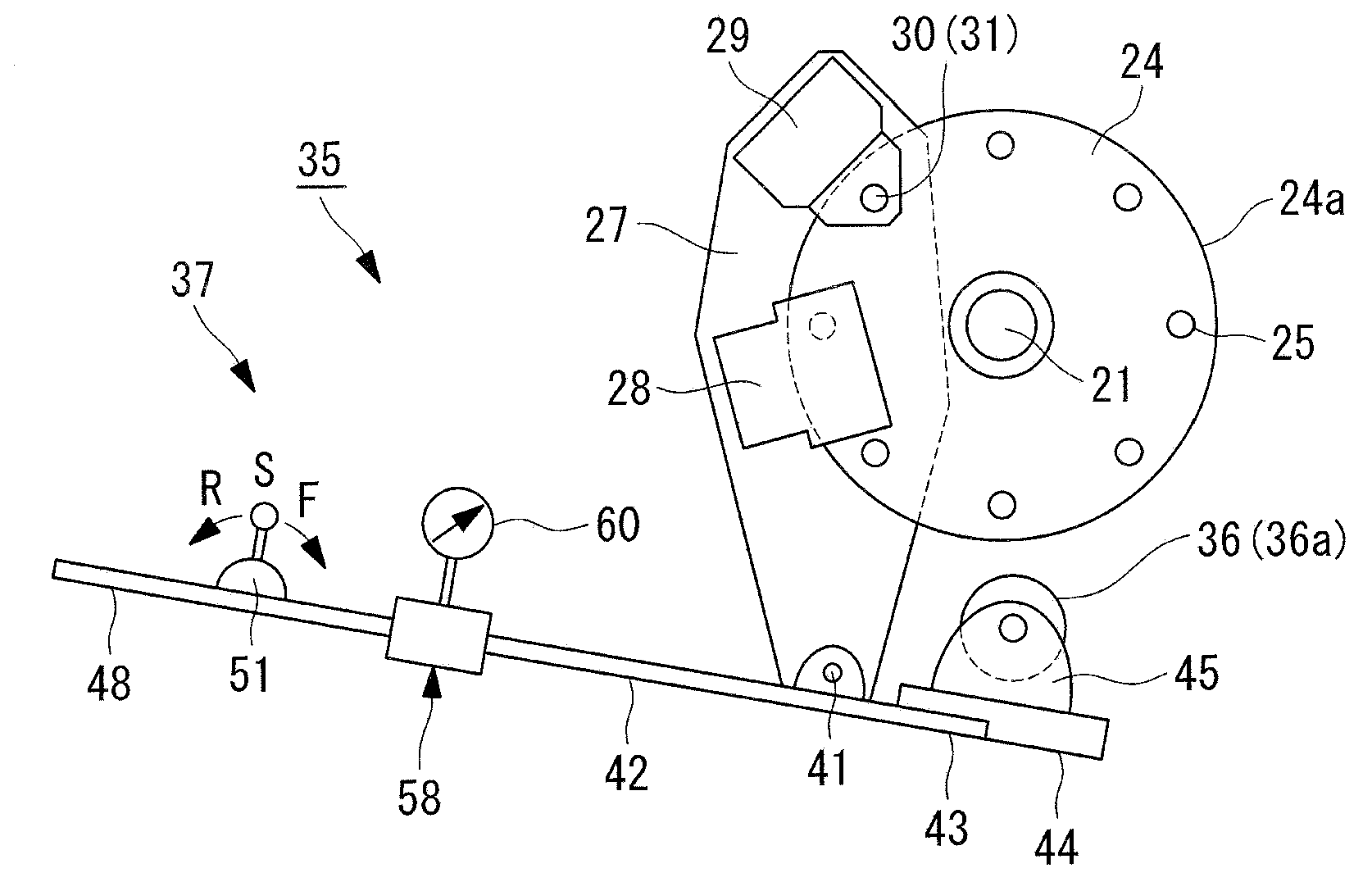
In order to enable the rotary vanes of a windmill to rotate to any position by means of a simple and low-cost configuration, and to prevent malfunctions even when excessive torque variation from the rotary vanes of the windmill is applied during gusty winds, a turning device (35) is characterized by being equipped with: a brake disk (24), which serves as driven-side friction pulley provided so as to rotate integrally on an output shaft (21) of a speed-increasing gear; a driving-side friction pulley (36), which is provided so as to be capable of moving between an engaged position (36b) wherein the outer circumferential surface (24a) of the brake disk (24) is frictionally engaged, and a free position wherein the driving-side friction pulley is separated from the outer circumferential surface (24a) of the brake disk (24); a pulley compression mechanism (37), which moves the driving-side friction pulley (36) from the free position to the engaged position (36b) in response to the manpower of the operator, causing the driving-side friction pulley to frictionally engage the outer circumferential surface (24a) of the brake disk (24); and a pulley-driving means (an electric motor or the like) which rotationally drives the driving-side friction pulley (36). When excessive torque variation is applied, the friction engagement between the brake disk (24) and the driving-side friction pulley (36) slips, and damage is avoided.

Description

technical field [0001] The present invention relates to a steering device for a wind turbine rotor that rotates the rotor blade to a desired position when the wind speed is low, and a wind power generator including the steering device for the wind turbine rotor. Background technique [0002] A standard rotor blade-type wind power generator includes a wind turbine rotor blade in which a plurality of wind turbine blades are attached to a rotor head serving as a rotation center. The rotor blade of the windmill is pivotally supported by a nacelle, and the nacelle is supported so as to be able to swivel at the upper end of the tower, and a speed increaser and a generator are provided inside the nacelle. When the rotor blades of the windmill are blown by the wind and rotate, the rotation is increased by the speed increaser and transmitted to the generator to generate electricity. For an upwind type wind power generation device, the nacelle is driven and controlled so that the rot...

Claims


Application Information

Patent Timeline
Patent Type & Authority Applications(China)
IPC IPC(8): F03D11/02F03D1/00F03D11/00
CPCF03D7/0268F05B2260/902F03D1/003Y02E10/725Y02E10/723F03D80/50F05B2260/31Y02E10/72F03D1/00F03D7/04
Inventor 沼尻智裕
Owner MITSUBISHI HEAVY IND LTD
Learn More