
Network device of optical network terminal and method of adjusting power of optical signals

一种网络装置、光学网络的技术,应用在多路复用系统的选择装置、选择装置、星型电磁网络等方向,能够解决光信号功率大、元件寿命降低、维修及元件成本提高等问题

Inactive Publication Date: 2014-03-26
ACCTON TECHNOLOGY CORPORATION
View PDF4 Cites 2 Cited by
  • Summary
  • Abstract
  • Description
  • Claims
  • Application Information

AI Technical Summary

Problems solved by technology

[0004] However, the distance between the above-mentioned optical network terminals (ONTs) and optical line terminals (OLTs) is usually not fixed, and when the optical network terminals send signals to the optical line terminals, they all output optical signals with the same power, so the distance between the optical The optical network terminal (ONT) far from the line terminal (OLT), the output optical signal power may not be enough to send the information to the optical line terminal (OLT) completely and without errors, resulting in signal transmission errors
Conversely, for an optical network terminal (ONT) that is closer to an optical line terminal (OLT), the output optical signal power may be too large to cause energy waste, and for components that transmit optical signals, higher power optical signals are emitted. It also leads to a reduction in the life of the component, resulting in an increase in maintenance and component costs
[0005] In addition, the optical network terminal (ONT) may have different distances from the optical line terminal (OLT) due to different functions or deployment locations, which will cause the above-mentioned disadvantages

Method used


Image

  • Network device of optical network terminal and method of adjusting power of optical signals
  • Network device of optical network terminal and method of adjusting power of optical signals
  • Network device of optical network terminal and method of adjusting power of optical signals

Examples


Embodiment Construction

[0036] In order to illustrate the present invention more clearly, preferred embodiments are given together with diagrams in detail as follows.

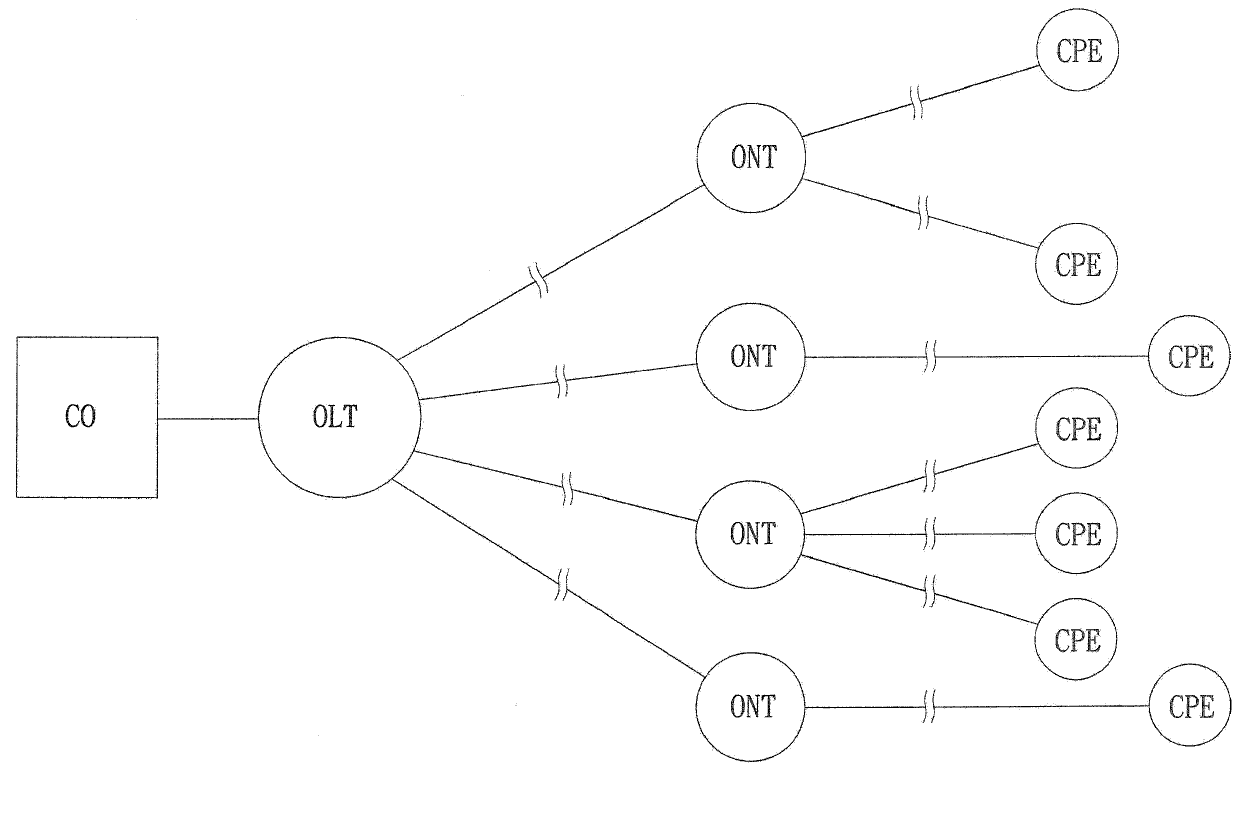
[0037] figure 1 It is a structural diagram of an optical fiber network system. In this embodiment, the optical fiber network system is a Gigabit Passive Optical Network (GPON) optical fiber network system, which includes an optical line terminal (Optical Line Terminal) OLT, and several optical network terminals ( Optical Network Terminal) ONT. Wherein, the optical network terminal (Optical Network Terminal) ONT may also be called an optical network unit (Optical Network Unit).

[0038] The OLT is used to receive an optical signal from a central office (Central Office, CO for short), and transmit the optical signal to each optical network terminal ONT.

[0039] The optical network terminal ONT is used to receive the optical signal sent by the optical line terminal OLT, and convert the optical signal into an electrical signal for tra...


PUM


Abstract

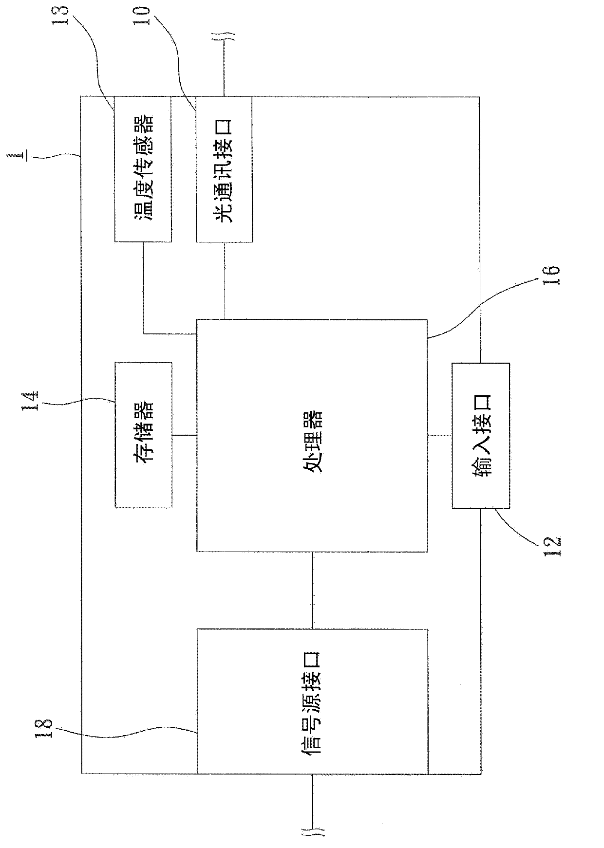
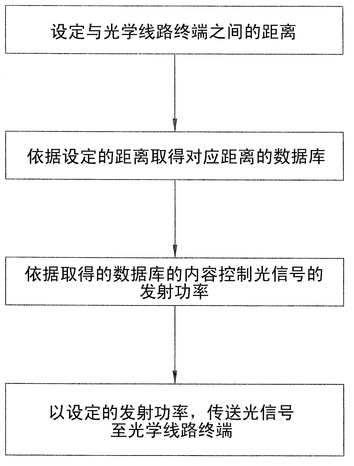
A network device of an optical network terminal (ONT) includes an optical communication interface, an input interface, a memory and a processor. Wherein the optical communication interface transmits optical signals with adjusted transmission power; the input interface is used to input a distance; the memory stores a plurality of distances, and a plurality of databases respectively correspond to the distances; the processor electrically connects to the optical communication interface, input interface and the memory, and is used to access the database in the memory corresponding to the inputted distance, and then adjust the transmission power of the optical communication interface according to the content in the database. In addition, a method of adjusting the power of optical signals is further provided in this invention.

Description

technical field [0001] The present invention relates to an optical network device, and more specifically refers to an optical network terminal (Optical Network Terminal, ONT) network device and a method for adjusting optical signal power. Background technique [0002] Due to the evolution of network transmission technology, transmission technology has evolved from electrical transmission technology to optical transmission technology, especially Gigabits Passive Optical Network transmission technology (Gigabits Passive Optical Network, referred to as GPON) has been widely used in network architecture to achieve network The signal can be transmitted quickly and the purpose of increasing the transmission bandwidth. [0003] In the GPON network system, it includes Optical Line Terminal (OLT for short) and Optical Network Terminal (ONT for short). Among them, the optical line terminal is responsible for transmitting the downlink signal of the central office (Central Office) to D...

Claims


Application Information

Patent Timeline
Patent Type & Authority Applications(China)
IPC IPC(8): H04B10/564
CPCH04B10/272H04B10/25H04Q11/0067H04Q2011/0079
Inventor 石懋澈
Owner ACCTON TECHNOLOGY CORPORATION
Learn More