A nonlinear control method for buck-boost converter system
A nonlinear control and converter technology, applied in control/regulation systems, DC power input conversion to DC power output, instruments, etc., can solve the problem of increasing software overhead, complex control strategies, and inability to completely eliminate transient overshoot of inductor current And other issues
- Summary
- Abstract
- Description
- Claims
- Application Information
AI Technical Summary
Problems solved by technology
Method used
Image
Examples
Embodiment Construction
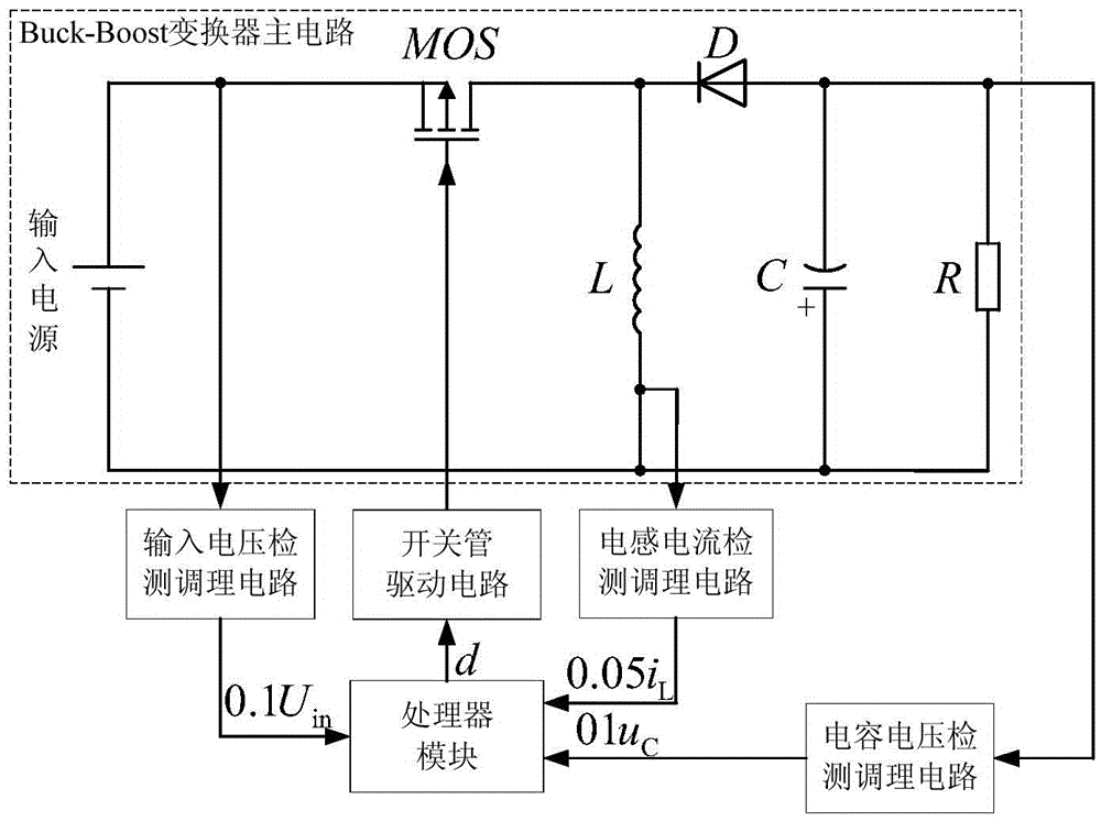
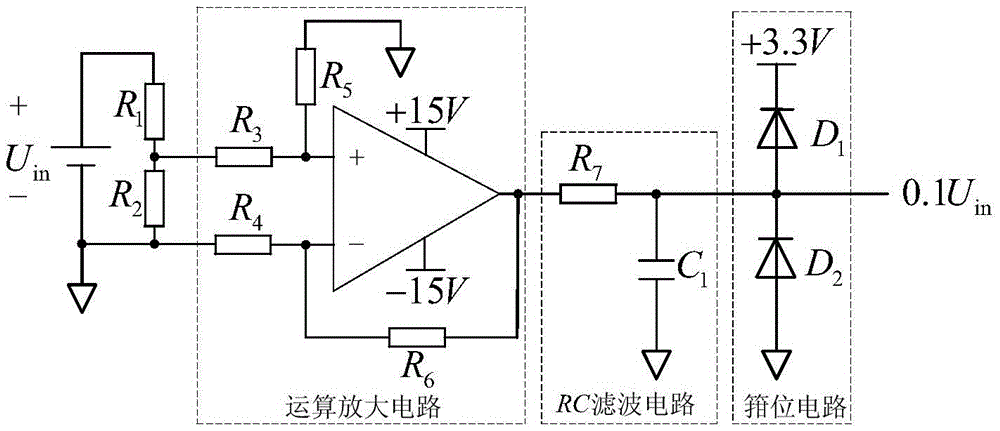
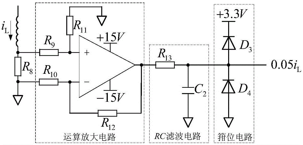
[0050] In this example, if figure 1 As shown, the composition of the Buck-Boost converter system includes: Buck-Boost converter main circuit, input voltage detection and conditioning circuit, inductor current detection and conditioning circuit, capacitor voltage detection and conditioning circuit, switch tube drive circuit and processor module, Buck- The main circuit of the Boost converter is composed of an input power supply, a switch tube MOS, an inductor L, a diode D, a capacitor C and a load R, and the switch tube MOS is a P-channel type;
[0051] The main circuit of the Buck-Boost converter is connected according to the following relationship: the anode of the input power is connected to the source of the switching tube MOS, the drain of the switching tube MOS, the cathode of the diode D and one end of the inductor L are connected together, and the anode of the diode D 1. The negative pole of the capacitor C is connected to one end of the load R, the negative pole of the ...
PUM
 Abstract
Description
Claims
Application Information
 - R&D
- Intellectual Property
- Life Sciences
- Materials
- Tech Scout
- Unparalleled Data Quality
- Higher Quality Content
- 60% Fewer Hallucinations
Browse by: Latest US Patents, China's latest patents, Technical Efficacy Thesaurus, Application Domain, Technology Topic, Popular Technical Reports.
© 2025 PatSnap. All rights reserved.Legal|Privacy policy|Modern Slavery Act Transparency Statement|Sitemap|About US| Contact US: help@patsnap.com


